Numbering device for molded or cast parts

a technology a molding machine, which is applied in the direction of manufacturing tools, moulding machines,foundry moulding apparatus, etc., can solve the problems of affecting the development of a numbering or marking device allowing the operator to change the mark from outside the molding machine, affecting the production efficiency of the machine, and affecting the quality of the product. , to achieve the effect of facilitating the change of the mark and maximizing production efficiency

Inactive Publication Date: 2007-08-07
GM GLOBAL TECH OPERATIONS LLC
View PDF13 Cites 16 Cited by
  • Summary
  • Abstract
  • Description
  • Claims
  • Application Information

AI Technical Summary

Benefits of technology

[0007]Consistent and consonant with the present invention, a numbering device which facilitates a changing of a mark as desired and maximizes production efficiency, has surprisingly been discovered.

Problems solved by technology

Typically, changing or updating the mark is difficult.
This procedure is not only time consuming, but requires elaborate safety precautions to protect the operator while inside the machine.
However, development of a numbering or marking device allowing the operator to change the mark from outside the molding machine has been hampered because of the durable construction necessary to withstand the tremendous jolts and pressure of the mold-forming operations.

Method used


Image

  • Numbering device for molded or cast parts
  • Numbering device for molded or cast parts
  • Numbering device for molded or cast parts

Examples


Embodiment Construction

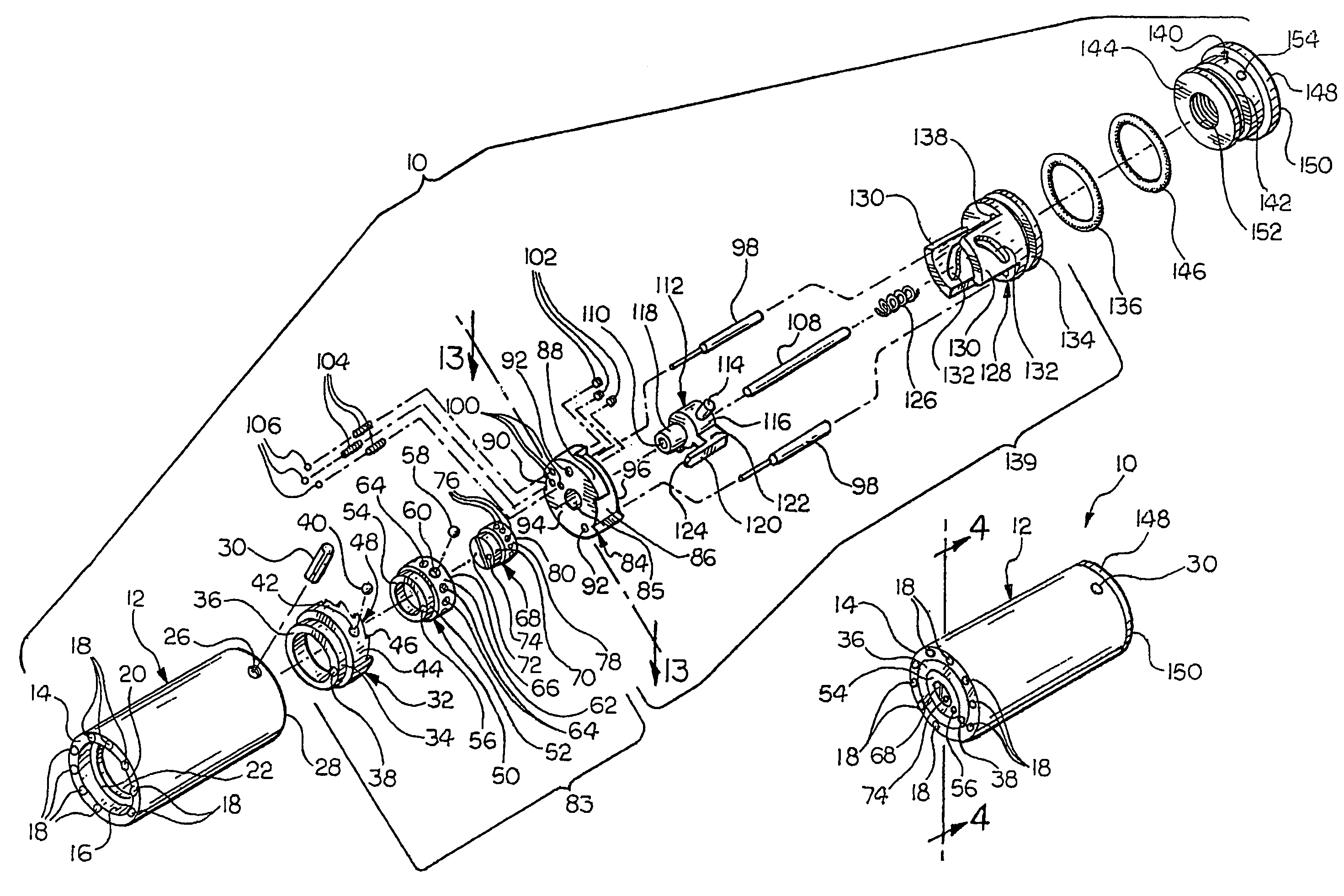
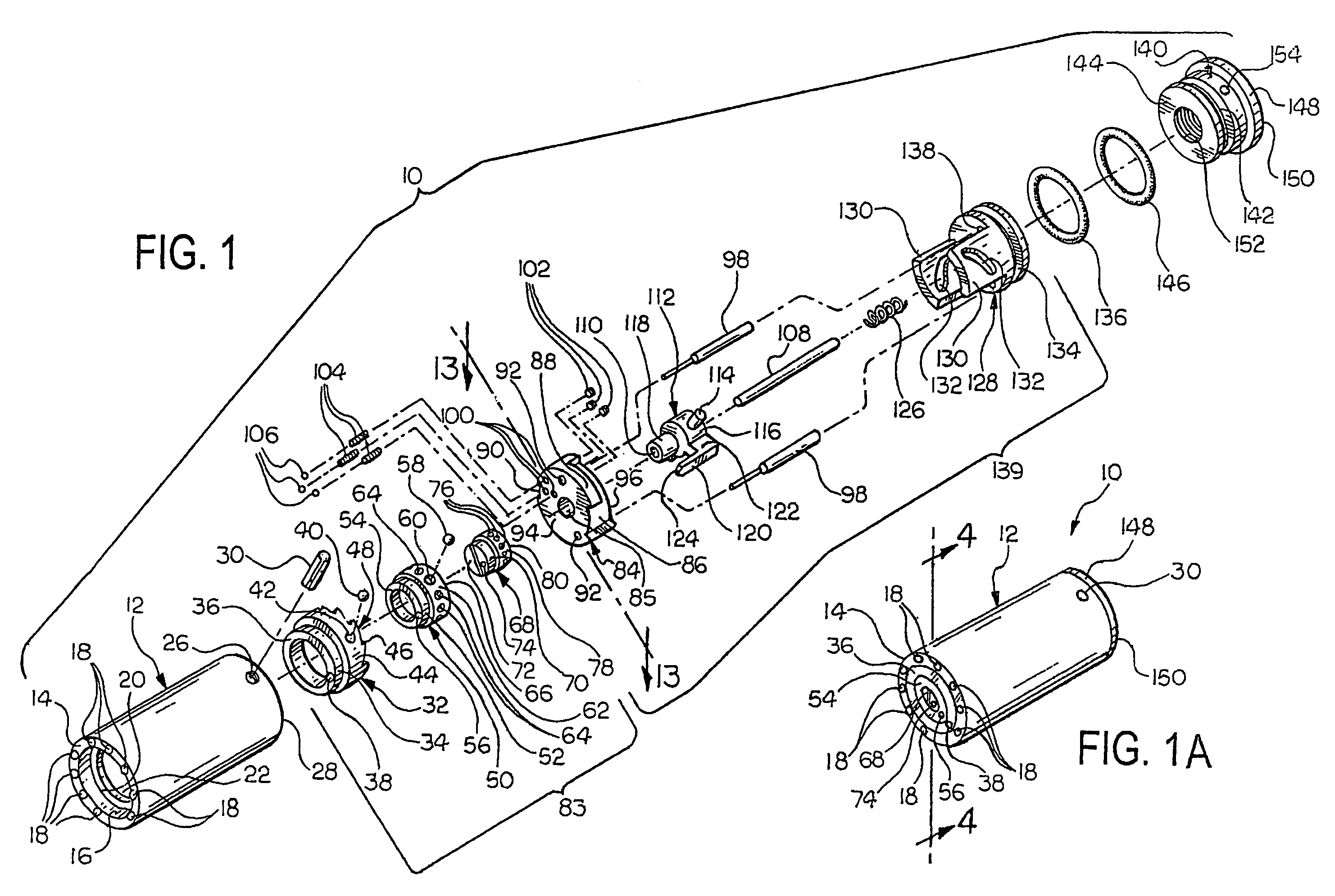
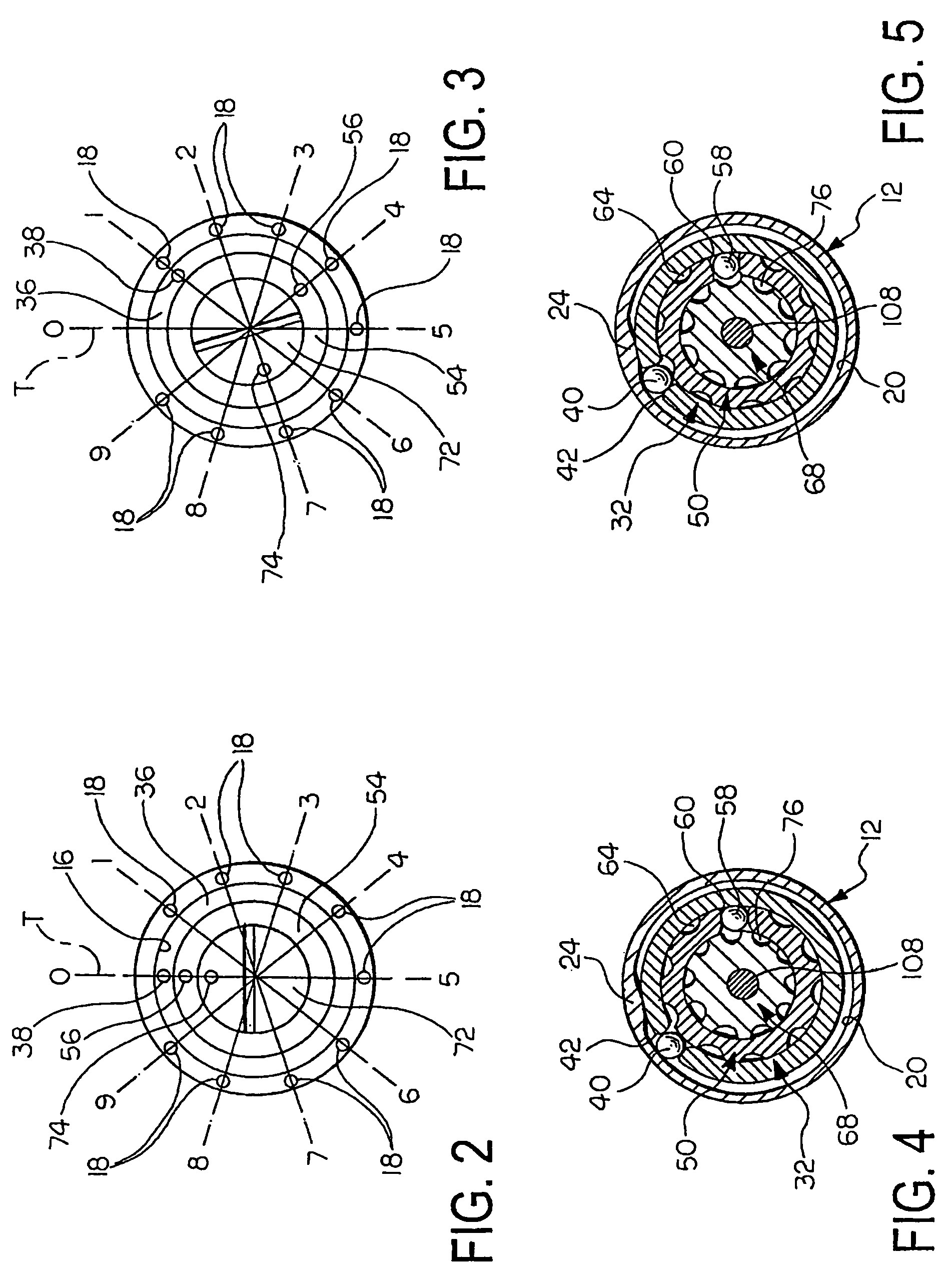
[0029]Referring now to FIG. 1, a numbering device 10 according to an embodiment of the invention is shown. The numbering device 10 includes a hollow main body 12. The main body 12 has a circular cross section in the embodiment shown. A first end 14 includes a radially inwardly extending lip 16. A plurality of spaced apart protuberances or indicia 18 is formed on an outer surface of the lip 16. As clearly illustrated in FIGS. 2 and 3, the protuberances 18 form a pattern representing numbered positions about the lip 16. A template T is shown overlaying the protuberances 18 and showing the numbered positions. A protuberance 18 is not formed at the location designated ‘0’ in order to assist in determining the proper orientation of the numbering system. It is understood that other markers instead of numerals could be used such as letters, for example, without departing from the scope and spirit of the invention. Additionally, more or fewer protuberances 18 can be used as desired. The pro...


PUM

PropertyMeasurementUnit
pressureaaaaaaaaaa
circumferenceaaaaaaaaaa
timeaaaaaaaaaa

Abstract

A numbering device is disclosed for marking molded cast parts, the device including a plurality of concentric cylinders having indicia disposed on an end thereof, the cylinders being rotatingly indexable to cause the indicia to move as desired to form the desired mark, the mark is then impressed into a sand mold and subsequently reproduced on the cast part.

Description

FIELD OF THE INVENTION[0001]The invention relates to a numbering device and more particularly a numbering device for marking molded cast parts wherein a mark is disposed on a sand mold and subsequently reproduced on the cast part.BACKGROUND OF THE INVENTION[0002]It is the practice in the metal casting industry to mark or label each casting to identify the casting for quality control purposes and to aid in obtaining an accurate production count. The identification marks generally contain such information as the hour of the day or the shift during which the casting was made. Proper identification requires the mark to be changed periodically in order to be accurate. Although other information may also be included, the present invention concerns itself with a portion of the mark which requires updating for each casting.[0003]A convenient method of displaying information is by a series of reference marks located about the circumference of a circle and an indicator mark located within the...

Claims


Application Information

Patent Timeline
Patent Type & Authority Patents(United States)
IPC IPC(8): B22C13/00
CPCB22C23/00
Inventor RIEKE, MICHAEL WILLIAM
Owner GM GLOBAL TECH OPERATIONS LLC
Why Eureka
Try Eureka