Recording tape cartridge

a technology for recording tapes and cartridges, applied in the field of recording tape cartridges, can solve problems such as the accuracy of mounting metal plates, and achieve the effect of improving the mounting accuracy

Active Publication Date: 2007-08-07
FUJIFILM HLDG CORP +1
View PDF3 Cites 8 Cited by
  • Summary
  • Abstract
  • Description
  • Claims
  • Application Information

AI Technical Summary

Benefits of technology

[0016]In view of the aforementioned, an object of the present invention is to provide a recording tape cartridge in which an influence of a gate portion to a metal plate which is attached firmly to a reel hub can be suppressed.
[0019]The gate portions, through which the resin material is introduced at the time of forming the main portion of the reel, are provided on the floor portion of the reel hub at the radial direction outer side of the metal plate. Thus, the gate portions do not interfere with the metal plate. As a result, this structure has no defects such as decreasing the area of the metal plate, requiring positioning of the metal plate with respect to the reel hub, or impairing mounting accuracy of the metal plate.
[0020]Accordingly, in the recording tape cartridge described above, the effect of the gate portions on the metal plate which is attached firmly to the reel hub can be reduced.
[0022]In the recording tape cartridge described above, the metal plate is attached firmly to the reel hub by insert molding. Thus, the profile accuracy of the metal plate is improved. In addition, since the gate portions are provided at the radial direction outer side of the metal plate, it is not necessary to provide through holes used for providing gate portions other than the through holes used for insert molding. Thus, the area of the metal plate is not reduced. Further, it is not necessary to position the metal plate in a direction in which the metal plate rotates within the mold so as to correspond to the gate portions. As a result, molding can be carried out easily.
[0025]In the recording tape cartridge described above, the plurality of gate portions is positioned at places which are spaced apart from the axial center of the reel hub (the main portion of the reel) such that the gate portions are positioned at even intervals on a predetermined circumference which is coaxial with the reel hub. Thus, the flow of the resin material is well-balanced. Hence, the setting for resin molding can be carried out with ease and the molding accuracy of (the main portion of) the reel can be improved.
[0027]In the recording tape cartridge described above, the gate portion is provided at the region where the reel gear is formed on the floor portion of the reel hub. Generally, the reel gear is formed at a thickened region of the floor portion. The gate portion is formed at such a thick portion. Therefore, the pressure is kept at the region where the reel gear is formed during the period at which the introduced resin material is cooled and cured. Thus, shrinkage caused by shrinkage of the region where the reel gear is formed can be prevented, and the molding accuracy of the reel gear is improved.

Problems solved by technology

As a result, this structure has no defects such as decreasing the area of the metal plate, requiring positioning of the metal plate with respect to the reel hub, or impairing mounting accuracy of the metal plate.

Method used


Image

  • Recording tape cartridge
  • Recording tape cartridge
  • Recording tape cartridge

Examples


Embodiment Construction

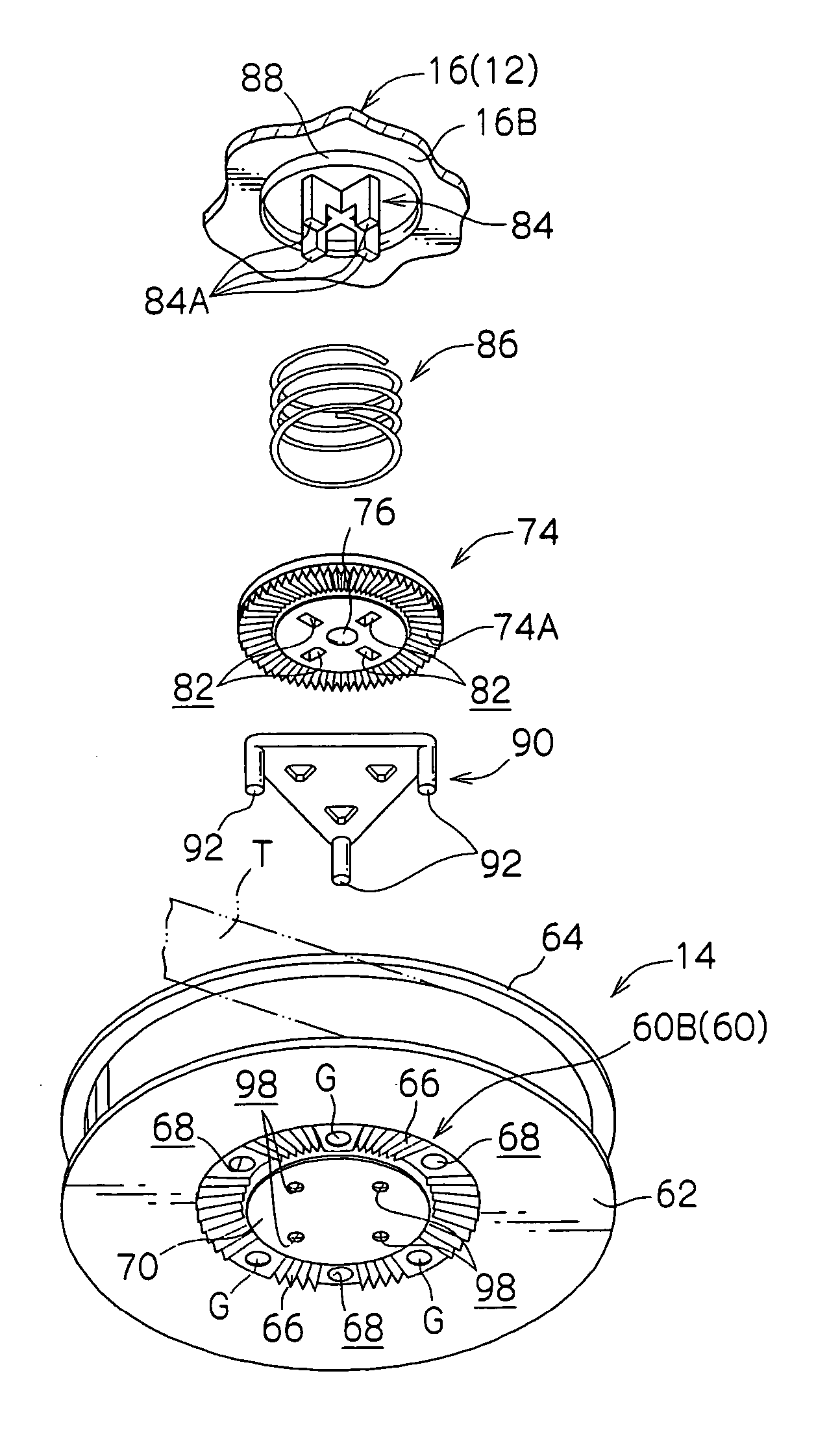
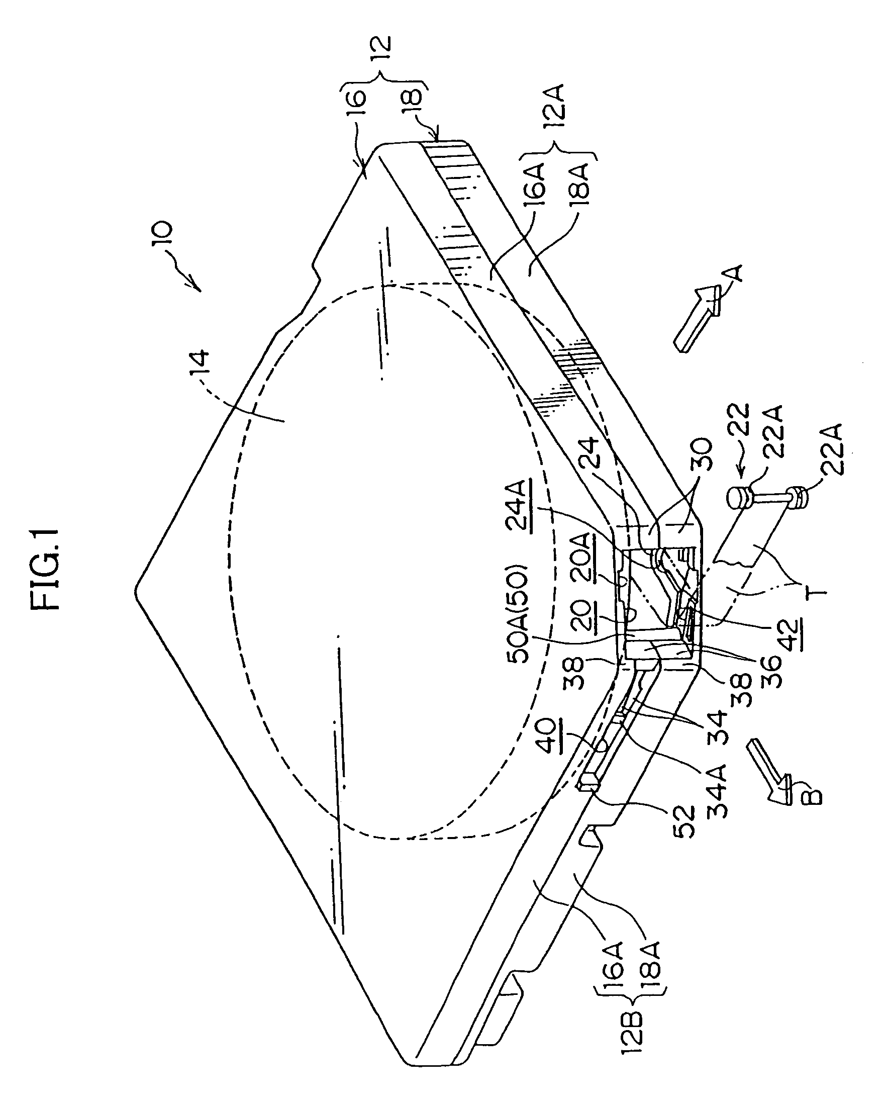
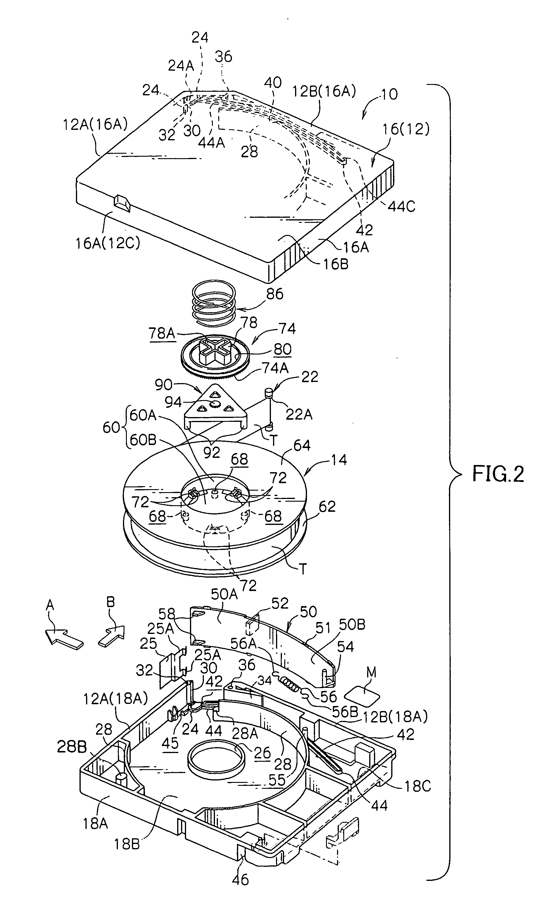
[0047]Hereinafter, a recording tape cartridge 10 relating to an embodiment of the present invention will be described on the basis of FIGS. 1 through 10. First, the basic, overall structure of the recording tape cartridge 10, the structures of an opening and a door, and the structures of a reel and a braking mechanism will be described. Then, the molding structure of a reel 14, which is a main portion of the present invention will be described. Note that, for convenience of explanation, the direction of loading the recording tape cartridge 10 into a drive device, which is denoted by arrow A, is the forward direction (front side) of the recording tape cartridge 10. Further, the direction of arrow B, which is orthogonal to arrow A, is the rightward direction.

Overall Structure of Recording Tape Cartridge

[0048]The overall structure of the recording tape cartridge 10 is shown in perspective view in FIG. 1. A schematic exploded perspective view of the recording tape cartridge 10 is shown ...


PUM

PropertyMeasurementUnit
circumferenceaaaaaaaaaa
thicknessaaaaaaaaaa
shapeaaaaaaaaaa

Abstract

A recording tape cartridge which can be loaded into a drive device having a reel on which a recording tape is wound and which is rotatably accommodated in a case, the reel including: a resin-formed main portion which includes a reel hub formed in a tubular shape having a floor, the recording tape being wound around an outer peripheral surface of the reel hub; and a substantially disc-shaped metal plate attached firmly to an outer surface of a floor portion of the reel hub, wherein a gate portion, through which a resin material is introduced at the time of molding the main portion, is provided at a radial direction outer side of the metal plate.

Description

CROSS-REFERENCE TO RELATED APPLICATION[0001]This application claims priority under 35 USC 119 from Japanese Patent Application No. 2004-2216, the disclosure of which is incorporated by reference herein.BACKGROUND OF THE INVENTION[0002]1. Field of the Invention[0003]The present invention relates to a recording tape cartridge which rotatably accommodates a reel on which a recording tape, such as a magnetic tape or the like, is wound.[0004]2. Description of the Related Art[0005]Recording tapes, such as magnetic tapes and the like, are used as external recording media of computers and the like. Little space is required for storage of the recording tape, and a large amount of information can be recorded thereon. A so-called single-reel recording tape cartridge is used which rotatably accommodates, within a case, a single reel on which such a recording tape is wound. (See Japanese Patent Application Laid-Open No. 63-251983 and Japanese Patent No. 3187022, for example.)[0006]The reel, whic...

Claims


Application Information

Patent Timeline
Patent Type & Authority Patents(United States)
IPC IPC(8): G11B23/07G11B23/087G11B23/04G11B23/113
CPCG11B23/044G11B23/113
Inventor IINO, WATARU
Owner FUJIFILM HLDG CORP
Why Eureka
Try Eureka