
Battery pack

a battery pack and molded resin technology, applied in the field of batteries, can solve the problems of affecting the service life of batteries, and affecting the reliability of battery packs,

Active Publication Date: 2007-08-07
SANYO ELECTRIC CO LTD
View PDF3 Cites 6 Cited by
  • Summary
  • Abstract
  • Description
  • Claims
  • Application Information

AI Technical Summary

Benefits of technology

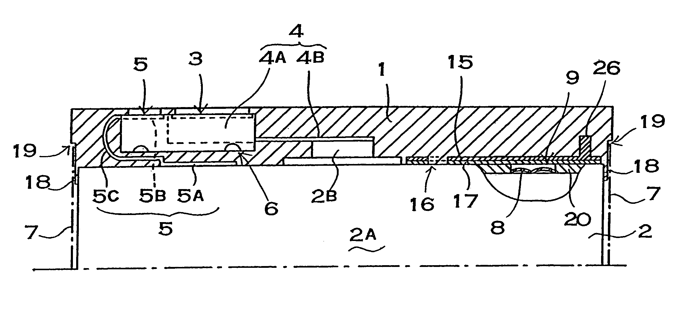
[0012]The insulating material can be a rigid plate material which will not deform under the pressure of molded resin region formation. Glass fiber reinforced epoxy plate can be used as the rigid plate material. The insulating material can be attached to the battery safety valve opening surface via double sided adhesive tape. In addition, the outline of the insulating material can be made smaller than the outer perimeter of the battery safety valve opening surface, and the molded resin region can attach to the safety valve opening surface at the perimeter of the insulating material to further strengthen attachment of the molded resin region to the battery. The insulating material can attach to the safety valve opening surface with a protruding electrode terminal of the battery. The insulating material through hole can be established between the protruding electrode terminal and the safety valve opening region.
[0014]An embedded projection on the insulating material can be a reverse tapered projection which becomes thicker or wider towards its end, a projection with hooks provided at its end, a rod with a plurality of projections provided on its surface, or a rod provided with cavities or through holes in its surface. The battery pack described above has the characteristic that the molded resin region and insulating material can be firmly joined and the molded resin region can be attached to the battery via the insulating material in a manner that will not de-laminate, while reliably preventing damage to the safety valve during molding. This is because the insulating material, disposed at the interface between the molded resin region and the battery safety valve opening surface, is provided with a through hole or embedded projection. For insulating material with a through hole, resin of the molded resin region is injected into the through hole, and that part of the molded resin region attaches to the battery safety valve opening surface. Synthetic resin which is injected into the insulating material through hole forms as a single piece with the molded resin region and is attached to the battery safety valve opening surface. This synthetic resin firmly attaches the insulating material to the safety valve opening surface and prevents its misalignment during molding. Properly aligned insulating material does not deform and protects the safety valve opening region. A safety valve protected by insulating material is not damaged by synthetic resin which forms the molded resin region. For insulating material with an embedded projection, the embedded projection becomes buried in the molded resin region and firmly joins the insulating material with the molded resin region via the embedded projection. By firmly joining the insulating material and the molded resin region, the embedded projection in the molded resin region reliably protects the safety valve opening region with the insulating material. A safety valve protected in this manner is not damaged by the synthetic resin which forms the molded resin region.
[0016]The embedded projection buried in the molded resin region has an anchoring effect connecting the insulating material to the molded resin region. However, the insulating material can be still more strongly connected with the molded resin region by forming the embedded projection to hook or latch into the molded resin region.

Problems solved by technology

Since a battery pack of this configuration is assembled by attaching the battery pack core in a fixed position within the external case, its manufacture requires considerable effort.
However, during the manufacturing process for this type of battery pack when molten synthetic resin is injected to form the molded resin region which locally covers the safety valve opening, the pressure of the injected synthetic resin can damage the safety valve.
However, it is difficult to reliably attach the molded resin region and insulating material in this type of battery pack.
Since the molded resin region attaches to the battery with insulating material disposed between the two, the battery pack has the drawback that attachment strength between the battery and molded resin region is degraded.
When attachment strength between the battery and molded resin region is degraded, the molded resin region can de-laminate from the battery during use rendering the battery pack unusable.
In addition, even though insulating material is attached to the safety valve opening, safety valve damage cannot reliably be prevented by insulating material which is easily deformed.

Method used


Image

  • Battery pack
  • Battery pack
  • Battery pack

Examples


Embodiment Construction

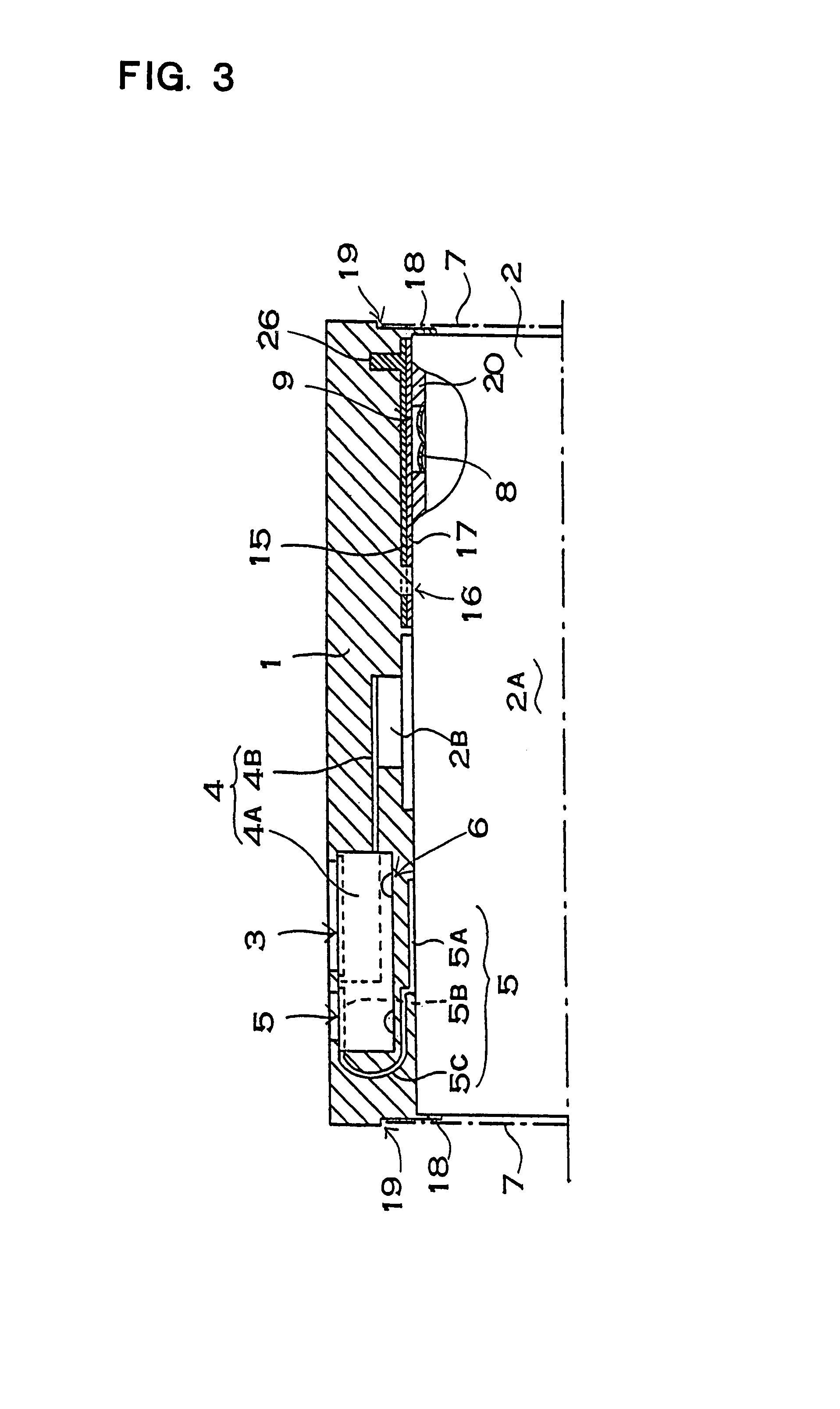
[0050]The battery pack of FIG. 3 has a safety valve 8, a safety valve opening surface 20 provided on the safety valve opening region 9, and this safety valve opening surface 20 is attached to a molded resin region 1. In the battery pack of FIG. 3, the molded resin region 1 is formed with a protection device 4 inserted during molding. Although not illustrated, components, such as a circuit board with protection circuitry mounted or with output terminals attached, can also be inserted during molding. Since the battery pack of FIG. 3 has the safety valve opening region 9 provided at the battery end plane with a protruding electrode terminal 2B, the molded resin region 1 is attached to that end plane. However, the safety valve opening region 9 may also be established at the battery end plane opposite the protruding electrode terminal, and the molded resin region can be attached to that end plane. Although not illustrated, a thin outline battery may have safety valves established on both...


PUM

PropertyMeasurementUnit
Pressureaaaaaaaaaa
Shapeaaaaaaaaaa
Perimeteraaaaaaaaaa

Abstract

The battery 2 of the battery pack is temporarily held in a mold 30 to form a molded resin region 1, synthetic resin injected into the mold cavity 31 to form the molded resin region 1 attaches to the battery 2, and the molded resin region 1 attaches to a safety valve opening surface 20 established at the battery safety valve opening region 9. Further, insulating material 15 is attached at the interface between the battery safety valve opening surface 20 and the molded resin region 1 in a position which closes off the safety valve opening region 9.

Description

[0001]This application is based on Applications No. 318062 filed in Japan on Oct. 31, 2002 and No. 379386 filed in Japan on Dec. 27, 2002, the contents of which are incorporated hereinto by reference.BACKGROUND OF THE INVENTION[0002]1. Field of the Invention[0003]This invention relates to a battery pack in which a battery pack core is insertion molded into a molded resin region. Specifically, this invention relates to a battery pack manufactured by temporarily holding the battery in a mold which forms the molded resin region, and by attaching the molded resin region to the battery by a process step which forms the molded resin region.[0004]2. Description of the Related Art[0005]Present battery packs are assembled by inserting a battery pack core, which is a battery and essential parts connected as a unit, into an external case formed of plastic. Since a battery pack of this configuration is assembled by attaching the battery pack core in a fixed position within the external case, it...

Claims


Application Information

Patent Timeline
IPC IPC(8): H01M2/12B29C45/14H01M6/50H01M50/574H01M50/583
CPCH01M2/08H01M2/1066H01M2/34H01M2/348H01M2/12H01M2200/106Y02E60/10H01M50/30H01M50/581H01M50/574H01M50/583H01M50/20
Inventor KAWABATA, KATSUHIKOWATANABE, ATSUSHINAKA, MASATSUGUKUBOTA, HIROMU
Owner SANYO ELECTRIC CO LTD
Learn More