Current sensor arrangement

a current sensor and coil technology, applied in the direction of instruments, measurement devices, measurement using dc-ac conversion, etc., can solve the problem of small error that is easily corrected, and achieve the effect of convenient positioning, convenient correction and efficient achievemen

Active Publication Date: 2007-08-07
S&C ELECTRIC
View PDF9 Cites 62 Cited by
  • Summary
  • Abstract
  • Description
  • Claims
  • Application Information

AI Technical Summary

Benefits of technology

[0007]Accordingly, it is a principal object of the present invention to provide a current sensor including a Rogowski coil provided in an assembly that is easily positioned about a conductor, e.g. without cutting the line or deenergizing the line.
[0009]These and other objects of the present invention are efficiently achieved by a current sensor including a Rogowski coil provided in an assembly that is easily positioned about a conductor, e.g. without cutting the line or deenergizing the line. In one arrangement, the Rogowski coil is formed about a split helical structure such that the ends of the Rogowski coil are not coincident. While this does introduce a small error in the current measurement, this small error is easily correctable by calibration and / or application software. The current sensor includes suitable insulation such that it can be placed about energized, high-voltage lines.

Problems solved by technology

While this does introduce a small error in the current measurement, this small error is easily correctable by calibration and / or application software.

Method used


Image

  • Current sensor arrangement
  • Current sensor arrangement
  • Current sensor arrangement

Examples


Embodiment Construction

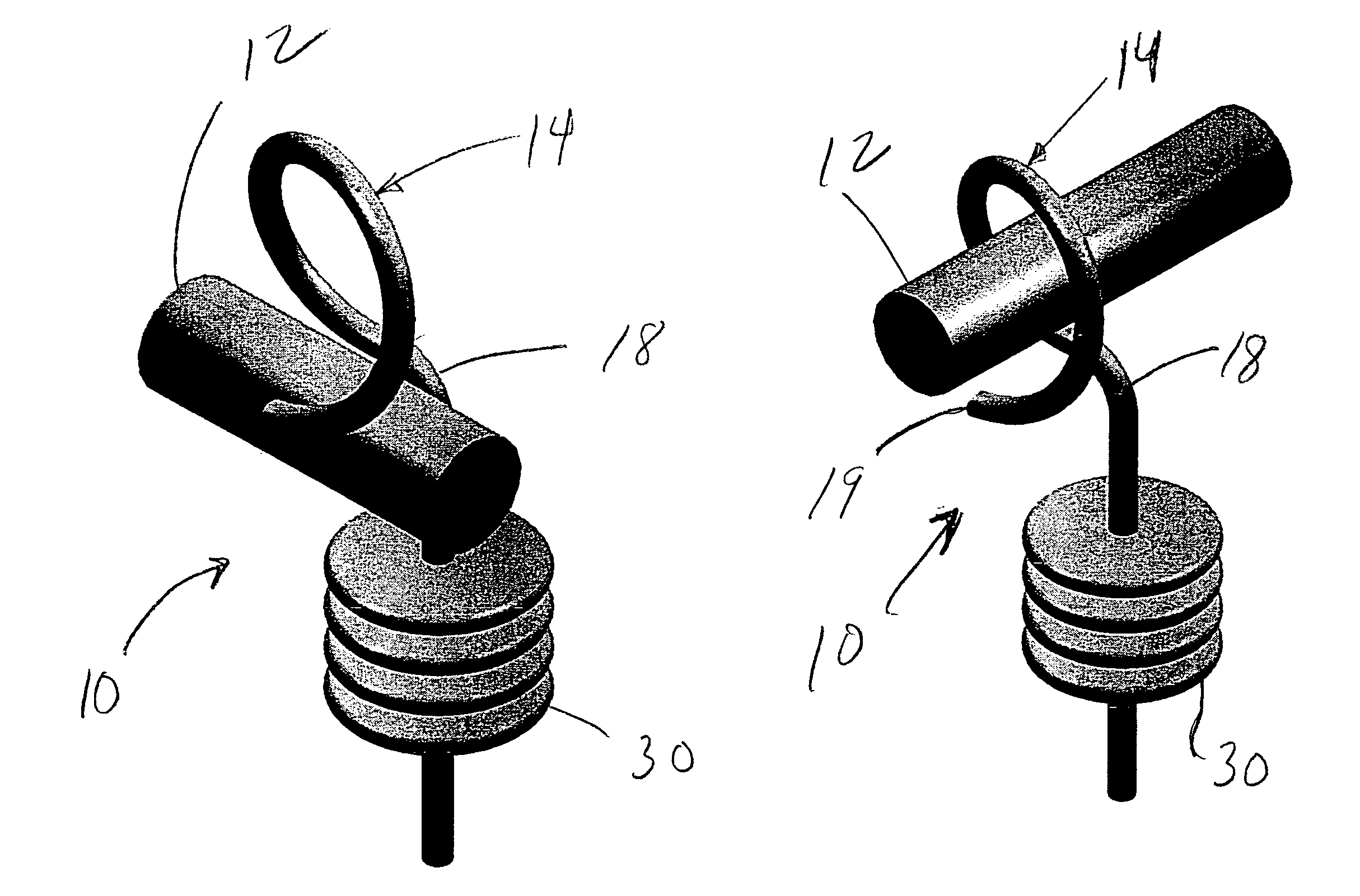
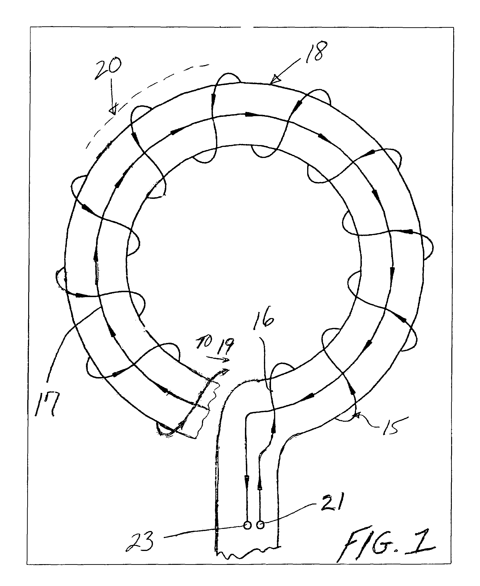
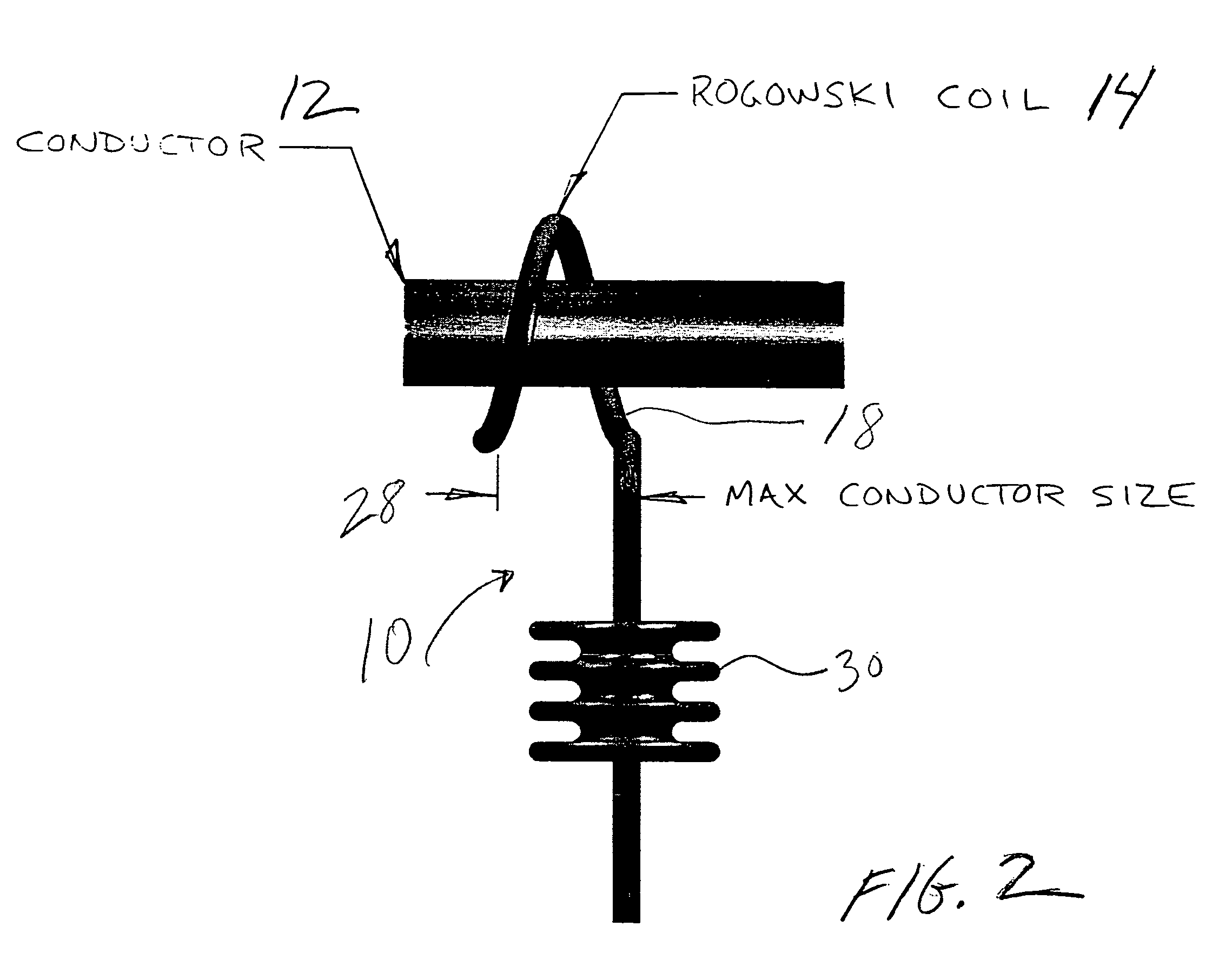
[0015]Referring now to FIGS. 1 and 2, the current sensor 10 of the present invention is useful to sense the current in a conductor 12 about which the current sensor 10 is positioned as shown in FIG. 2. As shown in FIG. 1, the current sensor 10 includes a Rogowski coil 14 (i.e. “air-cored” toroid) that is formed by winding turns 15 of wire 16 about and along a core 18, e.g. a rod. The core 18 is non-magnetic material, e.g. a diamagnetic or paramagnetic material of relative permeability of approximately 1 in a specific implementation. In the preferred embodiment, the core 18 is formed in a split helical configuration so as to define at least one complete turn and such that ends of Rogowski coil 14 are not coincident. While this does introduce a small error in the current measurement, this small error is easily correctable by calibration and / or application software. As shown in FIG. 1, in a specific embodiment, the Rogowski coil 14 includes a compensation turn 17 traversing around the ...


PUM


Abstract

A current sensor is provided including a Rogowski coil in an assembly that is easily positioned about a conductor, e.g. without cutting the line or deenergizing the line. In one arrangement, the Rogowski coil is formed about a split helical structure such that the ends of the Rogowski coil are not coincident. While this does introduce a small error in the current measurement, this small error is easily correctable by calibration and / or application software. The current sensor includes suitable insulation such that it can be placed about energized, high-voltage lines.

Description

[0001]This application claims the benefit of U.S. Provisional Application No. 60 / 641,542 filed on Jan. 6, 2005.BACKGROUND OF THE INVENTION[0002]1. Field of the Invention[0003]The present invention relates generally to current sensors and more particularly to a Rogowski coil provided in an assembly that is easily positioned about a conductor.[0004]2. Description of Related Art[0005]Various current sensors have been proposed for sensing the current flowing through a conductor. For example the voltage induced in a Rogowski coil about a conductor is processed by an integrator to provide a sensed current. The Rogowski coil is an “air-cored” toroidal coil formed by winding turns around a core or support structure of non-magnetic material, e.g. diamagnetic or paramagnetic material of relative permeability of 1. The conductor to be measured in then placed through the coil structure. In some arrangements, the Rogowski coil is formed as a split coil with some effect on the amplitude of the ou...

Claims


Application Information

Patent Timeline
Patent Type & Authority Patents(United States)
IPC IPC(8): G01R15/18
CPCG01R15/181
Inventor KOVANKO, THOMAS E.MOORE, JEFFREY A.SATPATHI, DEBASHIS
Owner S&C ELECTRIC
Why Eureka
Try Eureka