
Frontlit illuminated touch panel

a touch panel and frontlit technology, applied in the direction of identification means, lighting and heating apparatus, instruments, etc., can solve the problems of not using all the light supplied by many current devices, requiring satisfactory ito layer, and destroying most plastic substrates, etc., to achieve good optical properties, good light extraction characteristics, and good optical properties

Inactive Publication Date: 2007-08-07
3M INNOVATIVE PROPERTIES CO
View PDF55 Cites 22 Cited by
  • Summary
  • Abstract
  • Description
  • Claims
  • Application Information

AI Technical Summary

Benefits of technology

The present invention provides a frontlit touch panel that can be easily fabricated and combined with a reflective light valve to create a thinner, more efficient, and evenly illuminated device. The touch panel has a light extraction layer with a flat light exit face and containing buried reflective facets that extract supplied light from the guide through the light exit face. Compared to separate touch panels and front light guides, the frontlit touch panels have reduced overall thickness, higher transmission, and fewer interfaces. The frontlit touch panels are also more robust and less likely to be damaged. The invention also provides an illuminated touch panel display comprising a front light guide and a reflective light valve.

Problems solved by technology

The processing temperatures required to apply a satisfactory ITO layer will destroy most plastic substrates.
Many current devices do not use all of the light supplied by the light source.
These approaches can cause reduction in contrast, or can supply light at less than optimal angles to a light valve in the display.

Method used


Image

  • Frontlit illuminated touch panel
  • Frontlit illuminated touch panel
  • Frontlit illuminated touch panel

Examples


Embodiment Construction

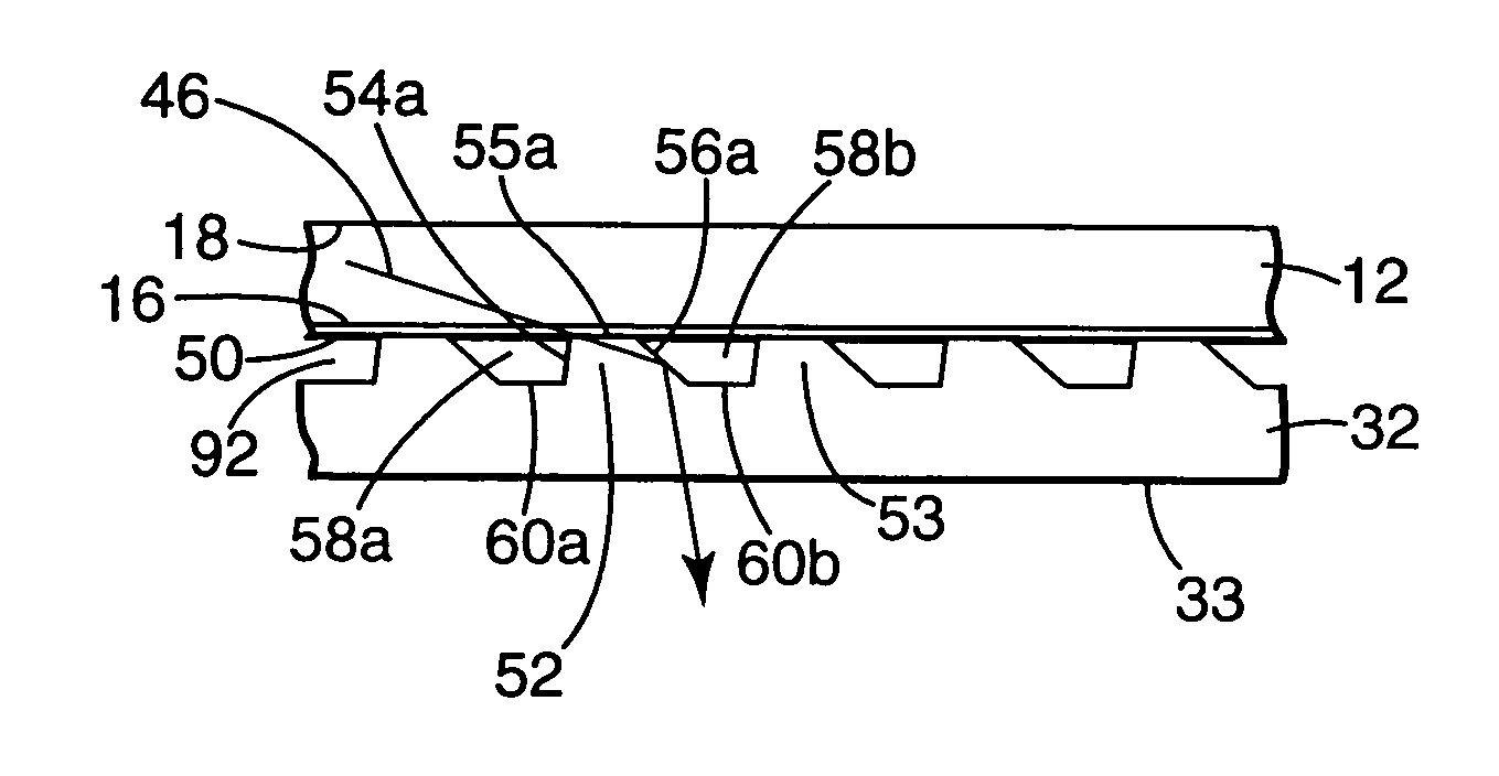
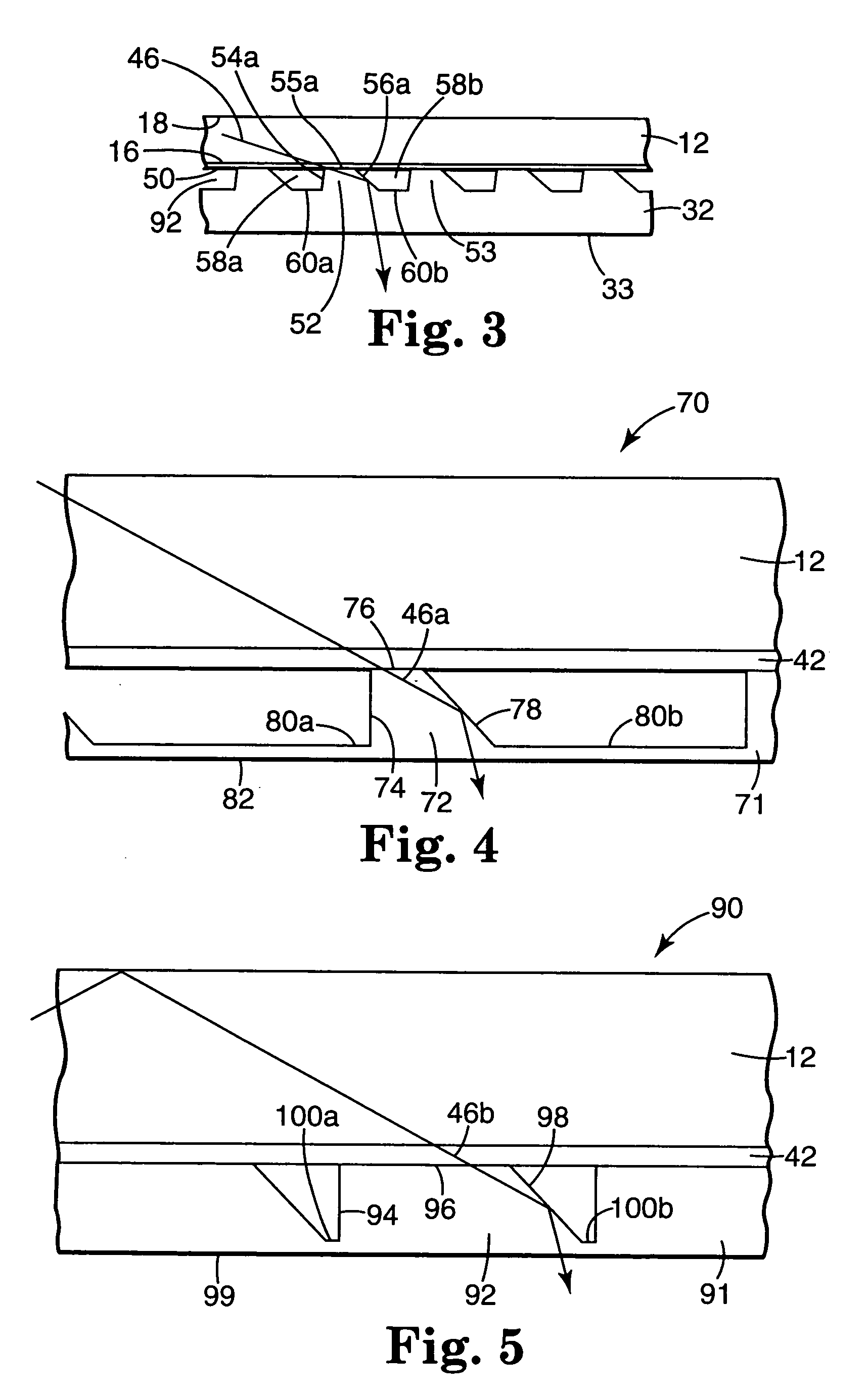
[0033]When terms such as “above”, “atop”, “upper”, “upward”, “beneath”, “below”, “lower” and “downward” are used in this application to describe the location or orientation of components in a display, these terms are used merely for purposes of convenience assuming that the display is viewed with its touch-sensitive surface facing generally upwards. These terms are not meant to imply any required orientation for the completed display or for the path taken by supplied or ambient light in actual use of the completed display. Some of the components of this invention and their relationship to one another can also conveniently be described by comparison to a reference plane. For purposes of this invention, the reference plane will be taken to be the plane formed by (or closely approximating) the light output face of the front light guide, which using the orientation convention described above would be the lower face of the light guide.

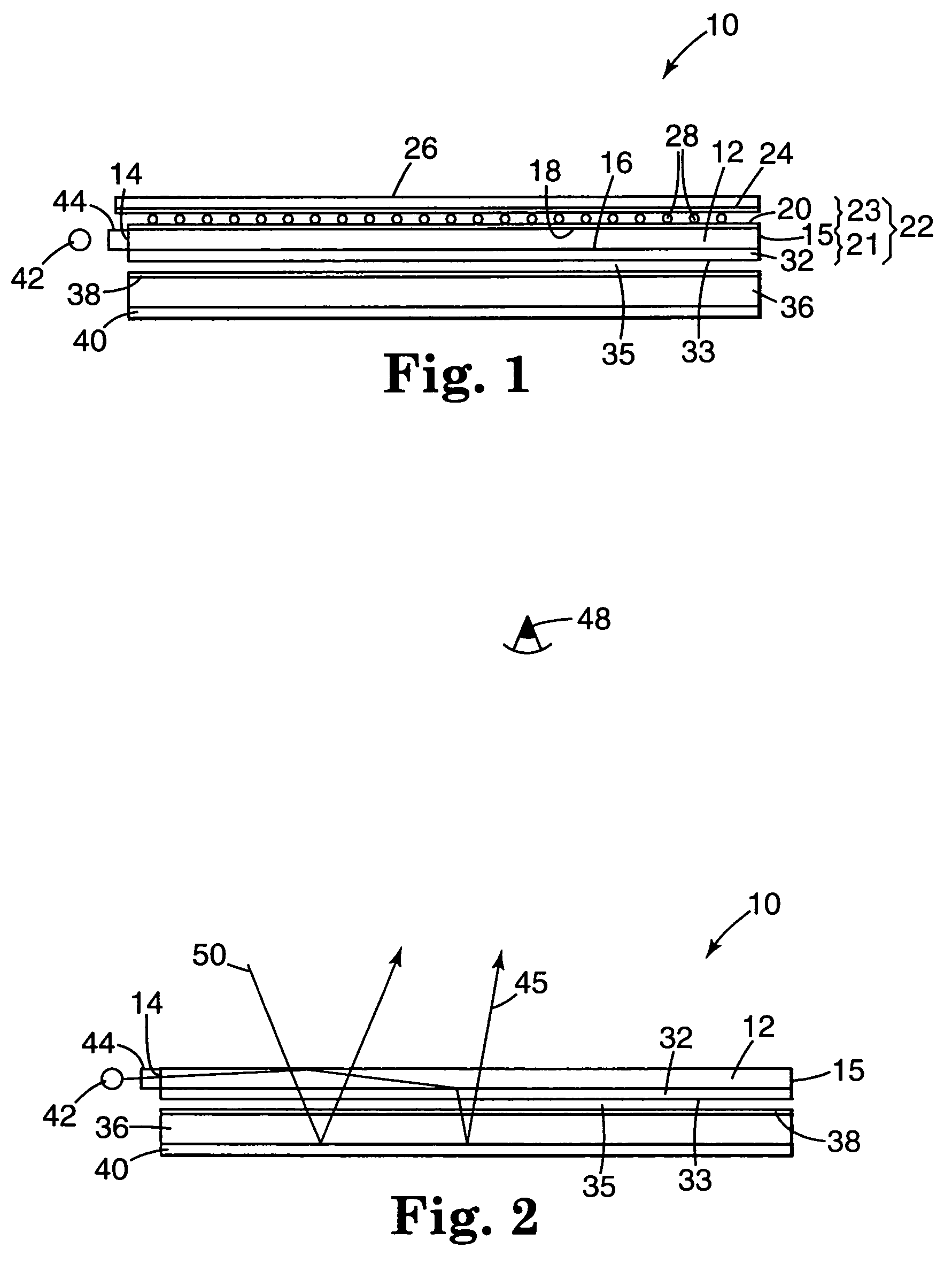
[0034]Referring now to FIG. 1, an illuminated touch p...


PUM

PropertyMeasurementUnit
angle of incidenceaaaaaaaaaa
thicknessaaaaaaaaaa
thicknessesaaaaaaaaaa

Abstract

A frontlit touch panel for use with a reflective light valve, comprising a front light guide having at least one light input face that supplies light to the guide, a viewing face, a light output face opposite the viewing face, and at least one component of a touch-sensitive transducer, the light output face having a light extraction layer thereon having a substantially flat light exit face and containing buried reflective facets that extract supplied light from the guide through the light exit face. The touch panel can be used with a light source, reflective light valve and suitable control electronics to form a compact, efficient illuminated touch panel display assembly.

Description

CROSS REFERENCE TO RELATED APPLICATION[0001]This application is a divisional of U.S. Ser. No. 09 / 827,732, filed Apr. 6, 2001, now U.S. Pat. No. 6,738,051, the disclosure of which is herein incorporated by reference.TECHNICAL FIELD[0002]This invention relates to touch panels and to electronic displays.BACKGROUND ART[0003]Flat panel displays are typically backlit by light guide slabs (often referred to as “backlights”) that provide uniform illumination to a transmissive light valve. The backlight may be the primary light source for the display, or a source of supplemental illumination in a predominantly reflective (often referred to as a “transflective”) display. Alternatively, flat panel reflective displays may be front-lit by a light guide slab (often referred to as a “frontlight” or “front light guide”) that provides uniform illumination from the viewing side of a reflective light valve. This allows elimination of the backlight and placement of a reflector in the light valve, there...

Claims


Application Information

Patent Timeline
Patent Type & Authority Patents(United States)
IPC IPC(8): G09G5/00F21V7/04G02B6/26G06F3/041F21V8/00G02F1/13357G06F3/033G09F9/00
CPCG02B6/0023G02B6/0053G06F3/041G02F2001/133616G06F3/0412G06F3/045G06F3/044G06F3/043G06F3/042G02F1/133616G06F3/03
Inventor BOYD, GARY T.PANKRATZ, STEPHAN J.
Owner 3M INNOVATIVE PROPERTIES CO
Learn More