Cylinder sleeve support for an internal combustion engine

a technology for internal combustion engines and cylinder sleeves, applied in the direction of cylinders, air cooling, sealing arrangements of engines, etc., can solve the problems of limiting the circulation of cooling fluid, affecting the heat transfer and cooling effect and the engine block material is not well-suited. , to achieve the effect of minimizing the lateral movement of the cylinder sleev

Inactive Publication Date: 2007-08-14
ELECTROMECHANICAL RES LAB
View PDF20 Cites 17 Cited by
  • Summary
  • Abstract
  • Description
  • Claims
  • Application Information

AI Technical Summary

Benefits of technology

[0010]Still another aspect of the present invention provides an apparatus for use within a liquid cooled reciprocating piston internal combustion engine that has a cylinder sleeve mounted to an engine block. The apparatus further has an engine head mounted to the engine block and a cooling fluid. The apparatus further includes means for maintaining a specified separation between the engine block and the engine head using a plate mounted between the engine block and the engine head where the plate is further mounted to the cylinder sleeve. The apparatus also includes means for cooling the cylinder sleeve using a groove in the plate that provides for direct contact between the cooling fluid and the cylinder sleeve; and means for minimizing lateral movement of the cylinder sleeve using the plate.

Problems solved by technology

Many designs utilize engine block materials that are not well-suited for use as the walls of the combustion cylinder.
A common problem with cylinder sleeves, however, is their tendency to deteriorate, especially near the top of the cylinder when the sleeve extends beyond the support limits of the engine block.
Previous inventions have attempted to support the upper portion of the cylinder sleeve using ring-shaped “block guards.” However, block guards create problems with heat transfer and restriction of circulating cooling fluid about the cylinder sleeve, and particularly about the upper portion of the cylinder sleeve adjacent the block guard.

Method used


Image

  • Cylinder sleeve support for an internal combustion engine
  • Cylinder sleeve support for an internal combustion engine
  • Cylinder sleeve support for an internal combustion engine

Examples


Embodiment Construction

[0037]For the purposes of promoting an understanding of the principles of the invention, reference will now be made to the embodiments illustrated in the drawings and specific language will be used to describe the same. It will nevertheless be understood that no limitation of the scope of the invention is hereby intended, such alterations and further modifications in the illustrated devices, and such further applications of the principles of the invention as illustrated herein being contemplated as would normally occur to one skilled in the art to which the invention relates.

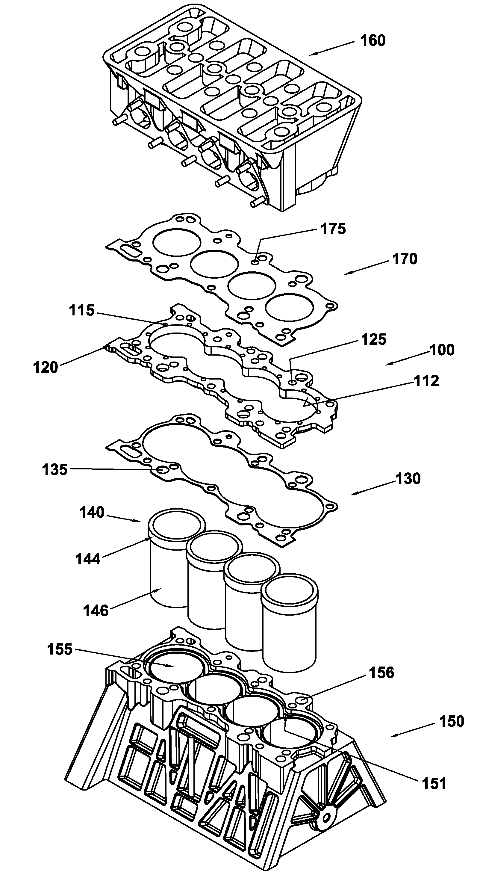
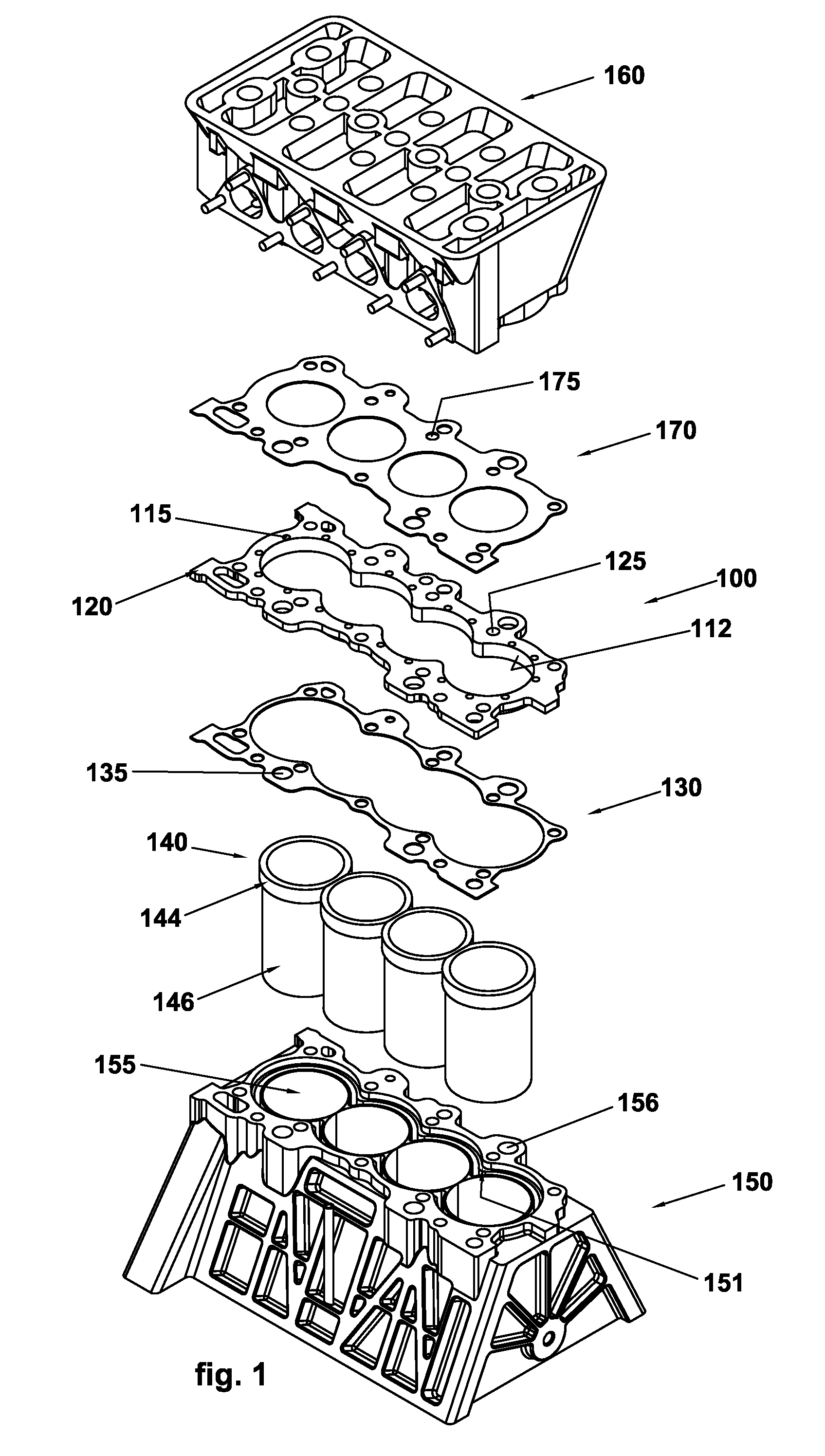
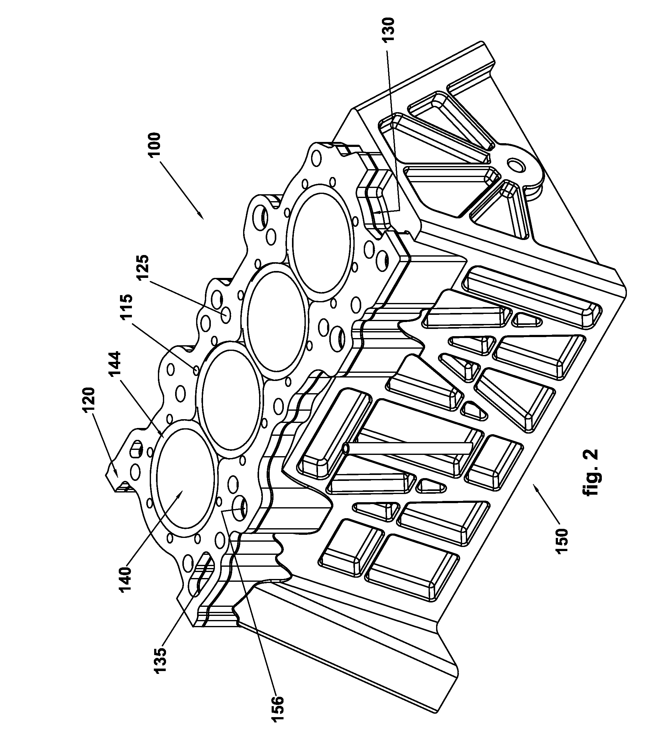
[0038]Referring to FIGS. 1-5, illustrated therein are select components of an open deck type internal combustion engine including a cylinder sleeve support plate 100 according to one embodiment of the present invention. The engine block 150 has four cylinder bores 155 into which respective cylinder sleeves 140 are placed. It should be understood, however, that the present invention is also applicable to engine b...


PUM


Abstract

The disclosed multi-cylinder, poppet-valved engine, has replacement cylinder sleeves larger than the original sleeves, and laterally supported near their upper ends by an aluminum alloy plate having a continuous flange or boss projecting into the cylinder block. The flange has an inner perimeter surface having a profile fittingly engaging upper exterior cylindrical surfaces of the sleeves providing lateral support to the sleeves and heat transfer from the sleeves to coolant and to the block. The flange further provides a coolant groove that circulates coolant around the perimeter of the cylinder sleeves to further the heat transfer from the sleeves to the coolant and to the block. The plate is sealed to the block and head with a spacing and gasketing to accommodate thermal expansion while avoiding combustion gas leakage at the cylinder sleeve tops.

Description

CROSS REFERENCE TO RELATED APPLICATIONS[0001]The present application is a continuation-in-part of U.S. application Ser. No. 10 / 624,876, filed Jul. 22, 2003, which claims the benefit of U.S. Provisional Application Ser. No. 60 / 472,589, filed on May 22, 2003, the contents of which applications are hereby incorporated herein by reference in their entirety.FIELD OF THE INVENTION[0002]The present invention generally relates to internal combustion engines, and more particularly relates to devices and methods for supporting one or more cylinder sleeves in an internal combustion engine.BACKGROUND OF THE INVENTION[0003]A traditional type of internal combustion engine utilizes a cylinder and reciprocating piston arrangement. A variable-size combustion chamber is typically formed with a cylinder that is effectively closed at one end and has a moveable piston at the other end. A combustible gas, or mixture of a combustible fluid and air, is introduced into the combustion chamber and then typica...

Claims


Application Information

Patent Timeline
Patent Type & Authority Patents(United States)
IPC IPC(8): F02F1/14F02F1/42F02F1/10F02F1/16
CPCF02F1/102F02F1/16F02F1/166
Inventor LIEBERT, JEFFREY W.
Owner ELECTROMECHANICAL RES LAB
Why Eureka
Try Eureka