Check patentability & draft patents in minutes with Patsnap Eureka AI!

Infusion device having piston operated driving mechanism and positive pressure reservoir

a driving mechanism and positive pressure technology, applied in the direction of suction devices, pressure infusion, medical preparations, etc., can solve the problems of limiting the functional longevity of the pump, increasing the maintenance requirements, and requiring a great deal of effort and expense in assembly and maintenance, so as to reduce the possibility of unfavorable medium leakage, reduce the risk of failure, and maintain the effect of constant output pressur

Active Publication Date: 2007-08-14
MEDTRONIC MIMIMED INC
View PDF31 Cites 145 Cited by
  • Summary
  • Abstract
  • Description
  • Claims
  • Application Information

AI Technical Summary

Benefits of technology

[0014]Preferred embodiments of the invention relate to such devices and drive mechanisms configured for implantation in a patient's body. Configurations described herein allow the drive mechanism to be designed, manufactured, assembled and maintained at reduced costs.
[0019]The infusion device further includes a drive mechanism having an inlet coupled in fluid flow communication with the positive pressure reservoir and an outlet coupled in fluid flow communication with the infusion device housing outlet. In one embodiment, a filter may be disposed between the reservoir and the drive mechanism (or as part of the inlet of the drive mechanism). In a further embodiment, expandable and compressible devices, such as one or more volume compensators or accumulators, which may also be, for example, accumulators, also may be disposed in the flow path between the positive pressure reservoir and the drive mechanism inlet, to dampen surges and ebbs in the flow.
[0023]Further embodiments may include a check valve to open and close the fluid flow path between the outlet chamber and the infusion site to provide additional protection against unwanted discharge of infusion medium from the infusion device. In preferred embodiments, the additional check valve may be located within the outlet chamber. However, in other embodiments, the check valve may be located elsewhere in the flow path between the outlet chamber and an infusion site, including within the outlet port, within a catheter attached between the outlet port and the infusion site or in any other suitable location.
[0024]Yet further embodiments may include additionally, or in the alternative, a conventional pressure regulating valve in the medium flow path. The pressure at which medium flows through the flow path is may be sensed by the pressure regulating valve. In one embodiment, the pressure regulating valve may have a low pressure cut-off point approximately equal to the pressure exerted by the positive pressure reservoir on the medium. Any medium flowing at a pressure below this low pressure cut-off point will be blocked by the pressure regulating valve. In this manner, any undesired leakage of the medium may be minimized.

Problems solved by technology

One problem associated with roller pumps is that they typically require a great deal of effort and expense in their assembly and maintenance in order to closely control the tolerances relating to the tube alignment and the occluding force applied by the rollers to various portions of the tube.
In addition, mechanical wear of elastomeric tubes resulting from the roller action involves increased maintenance requirements.
An additional problem associated with roller pumps is that mechanical friction produced by passing the roller or rollers over a fluid-swollen tube surface creates a large energy requirement, which can further limit the pump's functional longevity.
This may require increased design, manufacturing and assembly costs for the drive mechanism.

Method used


Image

  • Infusion device having piston operated driving mechanism and positive pressure reservoir
  • Infusion device having piston operated driving mechanism and positive pressure reservoir
  • Infusion device having piston operated driving mechanism and positive pressure reservoir

Examples


Embodiment Construction

[0041]The following detailed description is of the best presently contemplated mode of implementing the invention. This description is not to be taken in a limiting sense, but is made merely for the purpose of illustrating the general principles of embodiments of the invention. The scope of the invention is best defined by the appended claims.

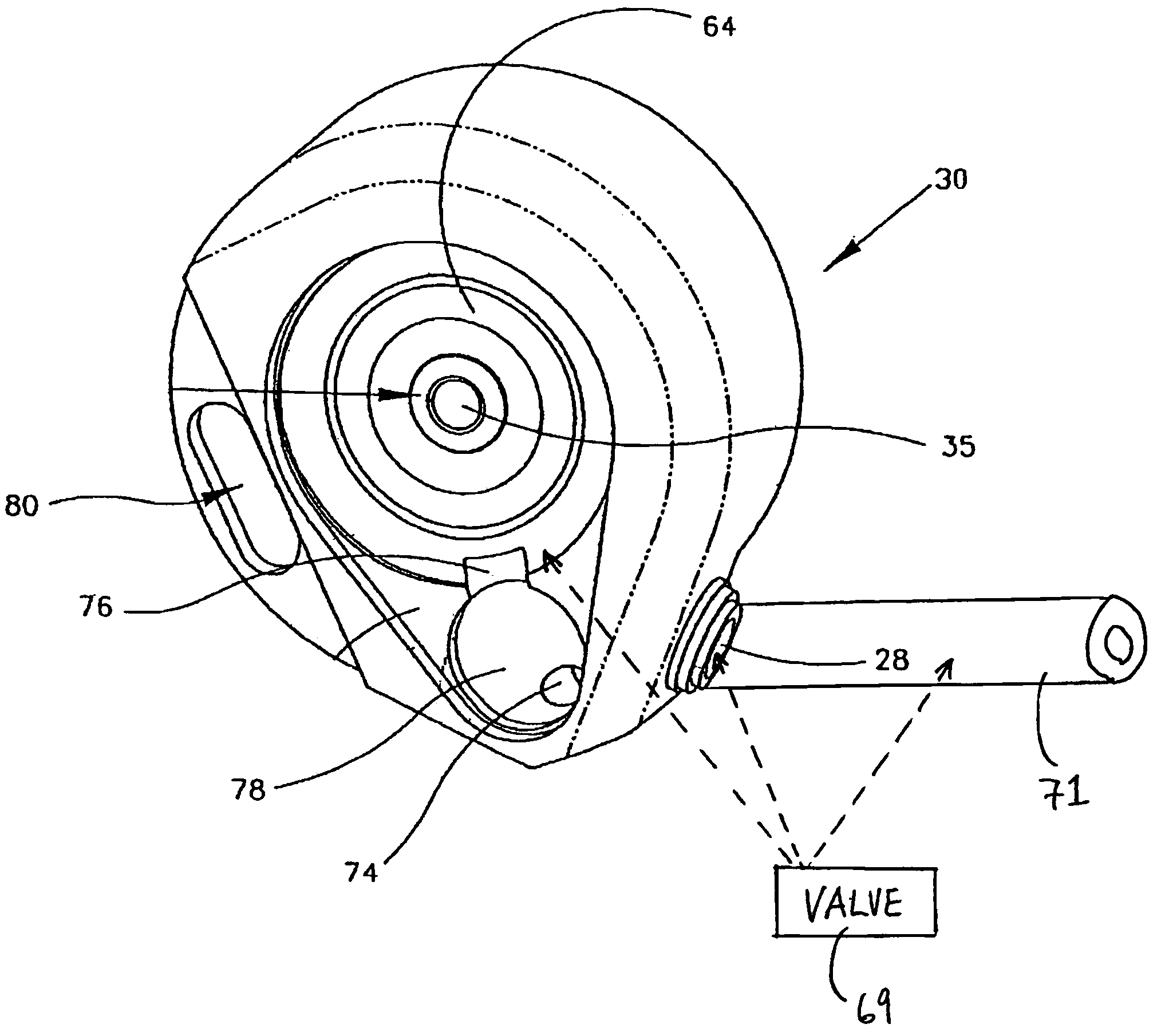
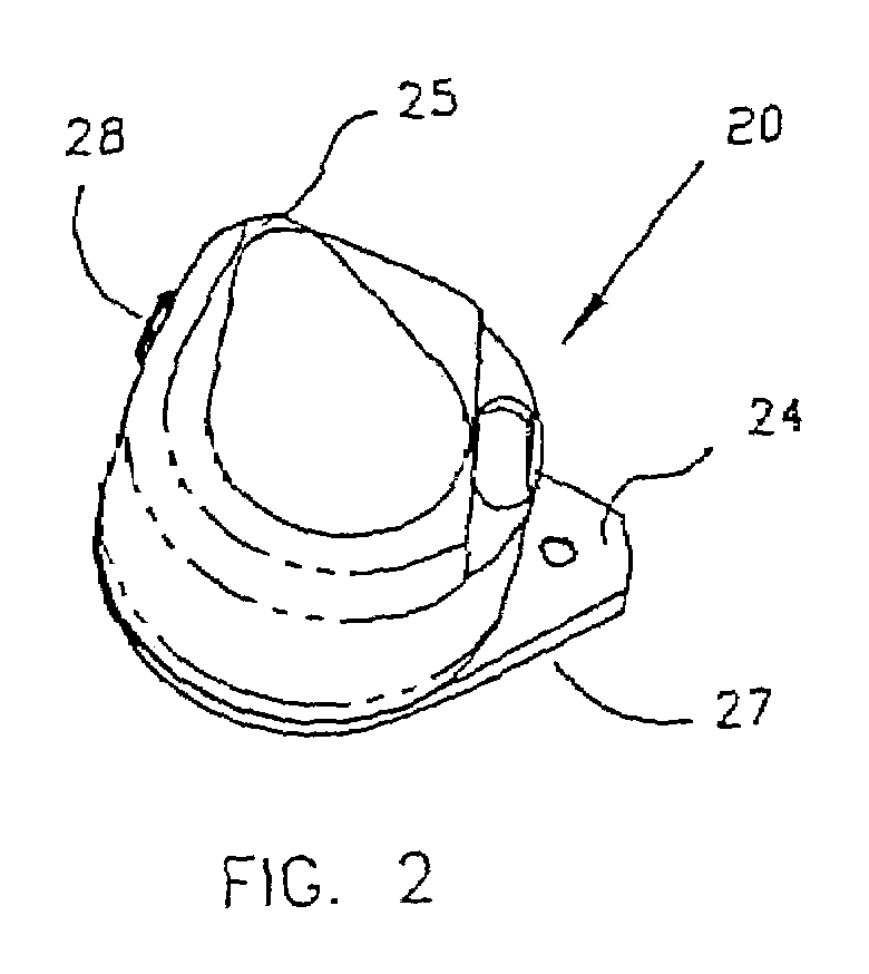
[0042]As discussed above, the present invention relates generally to infusion devices and methods and, in particular embodiments to implantable infusion devices and methods employing in combination a positive pressure reservoir and a piston-type driving mechanism functioning as a metering valve. Preferred embodiments of the invention relate to such devices and systems configured for implantation in a patient's body. Configurations described herein allow the infusion device to include a piston-type drive mechanism in combination with a positive pressure reservoir which avoids the effort and expense required in closely controlling tolerances rela...


PUM


Abstract

A piston-type drive mechanism in combination with a positive pressure reservoir for delivery of infusion medium. A coil capable of being electrically activated to provide an electromagnetic field. The coil surrounds a piston channel extending in an axial direction. The piston channel provides a passage for communication of infusion medium from the positive pressure reservoir to an outlet chamber. A piston is located within the piston channel and is moveable axially within the channel to a forward position. The piston is moved toward a retracted position, when the coil is not energized. As the piston is moved to its forward position, pressure moves a valve member into an open position. When the valve member is in the open position, medium from the piston chamber is discharged into the outlet chamber. An outlet is provided in flow communication with the outlet chamber, for discharging infusion medium from the outlet chamber.

Description

FIELD OF THE INVENTION[0001]The present invention relates generally to infusion devices and methods, in particular embodiments to implantable infusion devices and methods employing in combination a positive pressure reservoir and a piston-type driving mechanism functioning as a metering valve.RELATED ART[0002]Infusion devices, including implantable infusion devices, are frequently used for delivering drugs or other liquid medications over long periods of time to selected locations in the human body. These devices commonly include a drug reservoir having a catheter port and catheter means connected to the catheter port to transport the drug from the reservoir to a patient's anatomy by means of a drive mechanism. The drive mechanism propels the drug in some metered or constant flow dosage to the desired infusion site. Such devices also typically include a battery to power the drive mechanism as well as an electronic module to control the flow rate of the drive mechanism.[0003]A perist...

Claims


Application Information

Patent Timeline
IPC IPC(8): A61M1/00A61K9/22A61M5/142A61M5/145A61M5/155
CPCA61M5/14216A61M5/14276A61M5/1452A61M5/155
Inventor GRAY, JOHNBOSLEY, ROBERT W.
Owner MEDTRONIC MIMIMED INC
Features
  • R&D
  • Intellectual Property
  • Life Sciences
  • Materials
  • Tech Scout
  • Unparalleled Data Quality
  • Higher Quality Content
  • 60% Fewer Hallucinations
Learn More