Locomotive auxiliary power system

a technology of auxiliary power system and locomotive, which is applied in the field of locomotive, can solve the problems of incremental cost, forced to use relatively costlier regenerative rectifier drive, and insufficient satisfaction of either option,

Active Publication Date: 2007-08-14
GE GLOBAL SOURCING LLC
View PDF18 Cites 24 Cited by
  • Summary
  • Abstract
  • Description
  • Claims
  • Application Information

AI Technical Summary

Problems solved by technology

It is known that this power generating condition has necessitated either the addition of power dissipating resistor elements or, in lieu of using straightforward diode rectifiers, designers may be forced to use relatively costlier regenerative rectifier drives.
Either of these options is not fully satisfactory since each entails incremental costs and undue complexity for the auxiliary power system of the locomotive.
This consumes valuable and scarce space in the locomotive and requires careful analysis of mechanical resonances that may develop along the common shaft that mechanically interconnects these distinct alternators to the internal combustion engine of the locomotive.
Accordingly, if the voltage level of a common bus, or bus voltage, for powering both the traction motors and the auxiliary equipment is set to a voltage level appropriate for powering the traction motors, the auxiliary equipment may not be able to be directly connected to the bus because the bus voltage is different from the voltage required to power the auxiliary equipment.

Method used


Image

  • Locomotive auxiliary power system
  • Locomotive auxiliary power system
  • Locomotive auxiliary power system

Examples


Embodiment Construction

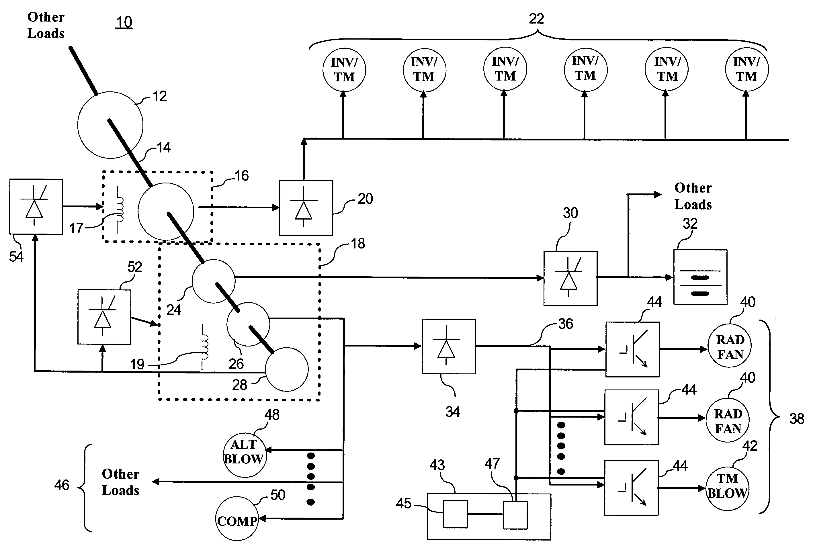
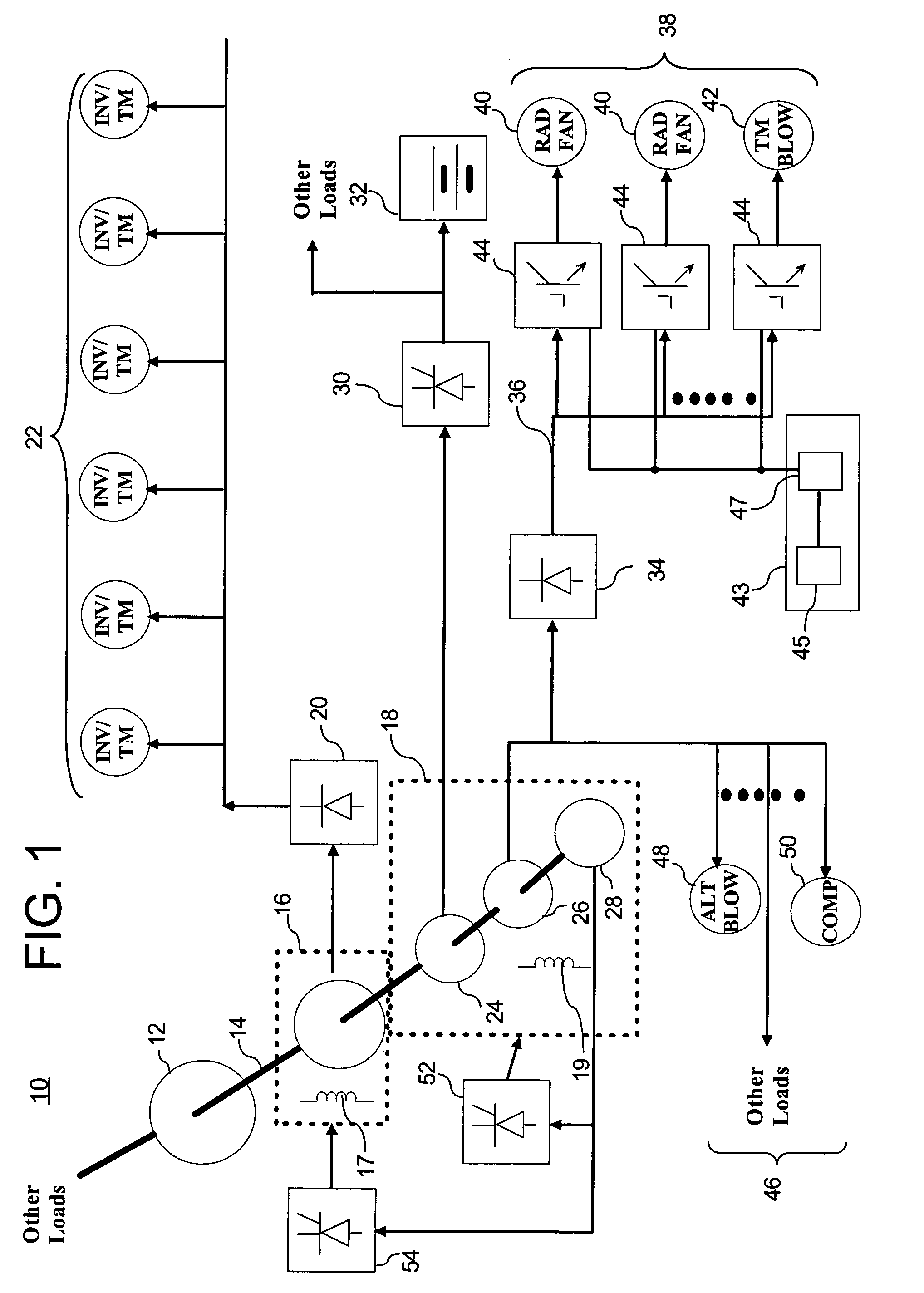
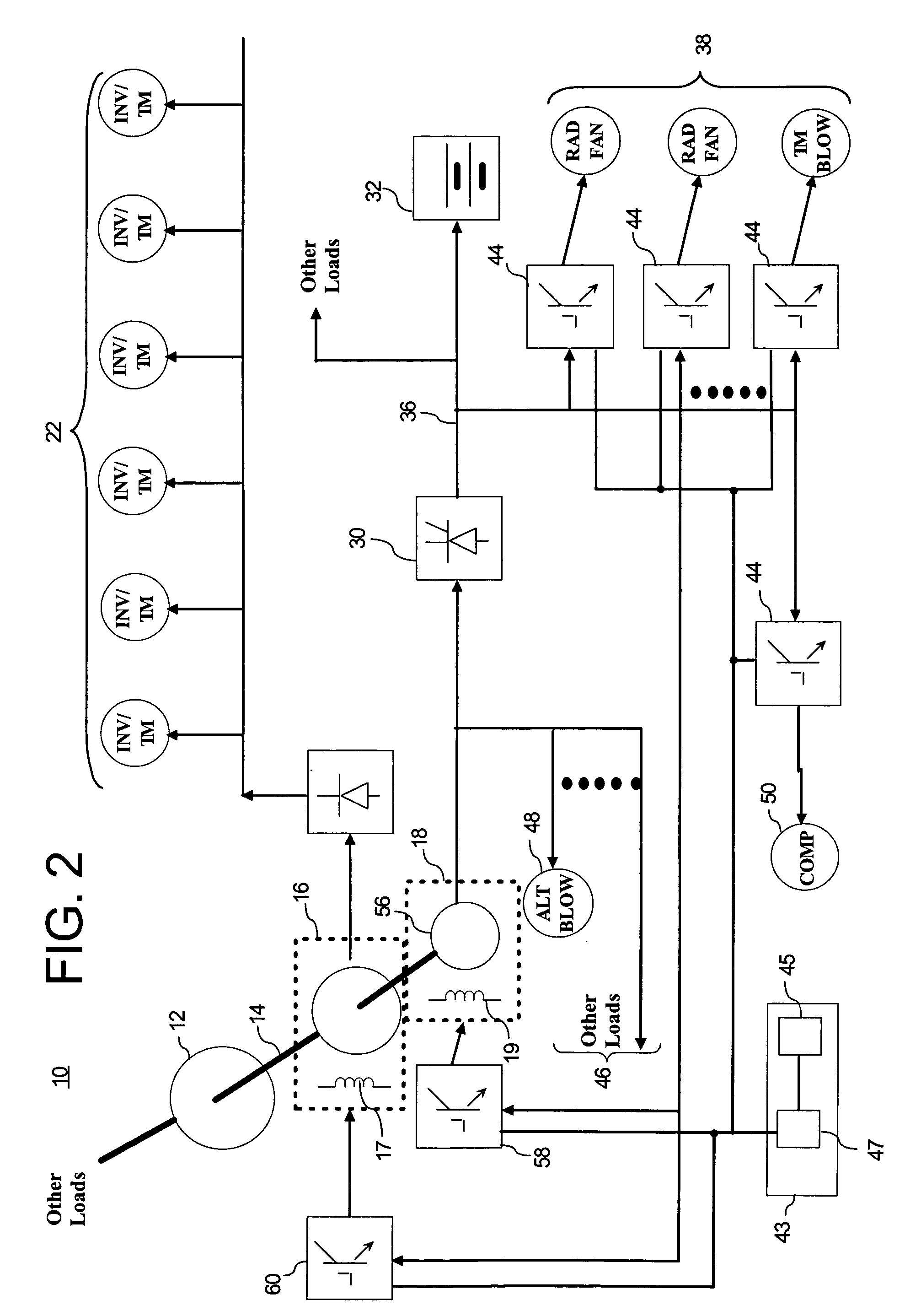
[0013]FIG. 1 is a block diagram schematic of an exemplary embodiment of a locomotive power system 10 in accordance with aspects of the present invention. This system 10 includes an engine 12 having a shaft 14 coupled to a main alternator 16 and an auxiliary alternator 18. The main alternator 16 may be electrically coupled via rectifier 20 to one or more traction motors 22. The main alternator 16 and the auxiliary alternator 18, being directly coupled to the engine 12 via the shaft 14, may generate alternating current (AC) having a frequency proportional to a speed of the engine 12. Accordingly, the output frequency of the auxiliary alternator 18 is a direct function of the diesel engine speed, such as the revolutions per minute (rpm) of the engine 12.

[0014]In one embodiment, the auxiliary alternator 18 includes three physically distinct alternators 24, 26, and 28, wherein each alternator is coupled to control respective auxiliary loads and is rated for a maximum power required to po...


PUM


Abstract

A locomotive auxiliary power system and control techniques for such a system are provided. In one exemplary embodiment the auxiliary power system includes an auxiliary alternator coupled to the internal combustion engine of the locomotive. The system further includes an auxiliary power bus powered by the auxiliary alternator. A rectifier may be connected between the auxiliary alternator and the auxiliary power bus. A plurality of devices may be electrically powered by the auxiliary power bus. A respective inverter is connected between the auxiliary power bus and each device, wherein the inverter provides a path for diverting electrical power generated during a transient mode by at least one the plurality of devices. In one exemplary embodiment, the auxiliary alternator is made up of a single alternator connected through a single shaft to the internal combustion engine.

Description

BACKGROUND OF THE INVENTION[0001]The present invention is generally related to locomotives and, in particular, to an auxiliary power system of a locomotive.[0002]A diesel-electric locomotive typically includes a diesel engine coupled to drive a main alternator and a set of auxiliary alternators, made up of several physically distinct alternators. The main alternator is coupled to power one or more traction motors, and the auxiliary alternator set is coupled to power locomotive auxiliary electrical equipment. The auxiliary alternator set may include a first alternator for powering a battery, a second alternator for powering auxiliary equipment, and a third alternator for providing field excitation to the auxiliary alternator and the traction alternator.[0003]It is known to provide variable frequency and / or voltage by way of inverters so that the auxiliary equipment may be driven at any speed below or above the engine speed. The auxiliary equipment is generally operable in an electric...

Claims


Application Information

Patent Timeline
Patent Type & Authority Patents(United States)
IPC IPC(8): H02J7/30H02J15/00
CPCB60L1/003B60L11/08Y02T10/70B60L2200/26B60L50/13
Inventor KUMAR, AJITH KUTTANNAIRIOANNIDIS, DIMITRIOS
Owner GE GLOBAL SOURCING LLC
Why Eureka
Try Eureka