Method and apparatus for improved current focusing in galvanic resistivity measurement tools for wireline and measurement-while-drilling applications

a technology of galvanic resistivity and measurement tools, applied in the field of well logging, can solve the problems of high measurement errors if not considered, incomplete focusing effect, and inability to provide complete coverage, so as to minimize the current flow

Active Publication Date: 2007-08-14
BAKER HUGHES INC
View PDF20 Cites 59 Cited by
  • Summary
  • Abstract
  • Description
  • Claims
  • Application Information

AI Technical Summary

Benefits of technology

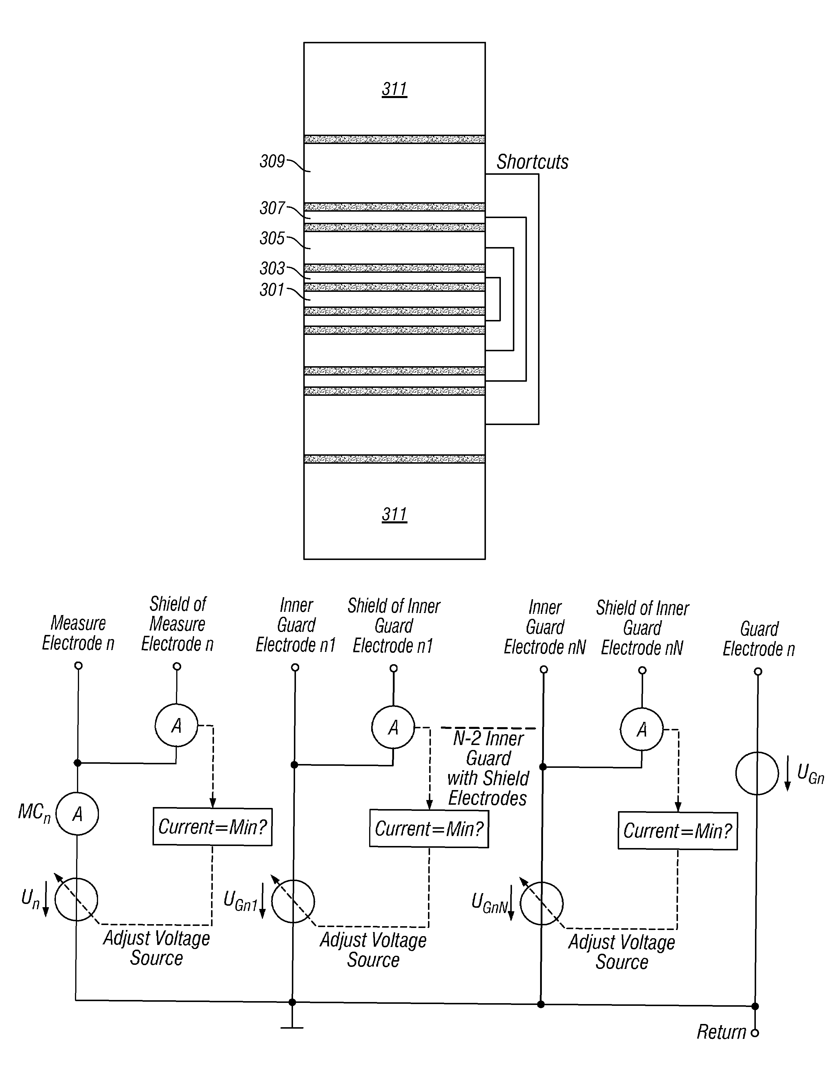
[0017]Another embodiment of the invention is a computer readable medium for use with a logging tool used in a borehole in an earth formation. The logging tool includes a measurement electrode which conveys a measure current into the earth formation and a guard electrode which focuses the measure current. The logging tool also has shielding electrode positioned between the guard electrode and the measurement electrode. The medium includes instructions enabling minimizing a current flow between the measurement electrode and the shielding electrode, and the determination of an apparent resistance from the measure current and a potential of the guard or measurement electrode.

Problems solved by technology

Higher driving potential differences may lead to currents from guard to measurement electrode or vice versa passing the borehole fluid around the tool, which would completely destroy the focusing effect and lead to high measurement errors if not considered.
The Dory patent discloses the use of an acoustic sensor in combination with pad mounted electrodes, the use of the acoustic sensors making it possible to fill in the gaps in the image obtained by using pad mounted electrodes due to the fact that in large diameter boreholes, the pads will necessarily not provide a complete coverage of the borehole.
In natural environments, the formation is filled with fluid whose chemical composition is not completely controllable, it is almost impossible to predict exactly contact impedances for measurement and guard electrodes.
The focusing effect will be weakened or damaged whenever the potentials of guard and measurement electrodes beyond the impedance layer become different.
This difference could cause a current to flow through the mud between the electrodes.
The problem of contact impedances during logging while drilling / measurement while drilling (LWD / MWD) applications differs from that of wireline applications because of the significantly higher mechanical strain of the measurement tool during operation.
Bonner does not address the issue of contact impedances.

Method used


Image

  • Method and apparatus for improved current focusing in galvanic resistivity measurement tools for wireline and measurement-while-drilling applications
  • Method and apparatus for improved current focusing in galvanic resistivity measurement tools for wireline and measurement-while-drilling applications
  • Method and apparatus for improved current focusing in galvanic resistivity measurement tools for wireline and measurement-while-drilling applications

Examples


Embodiment Construction

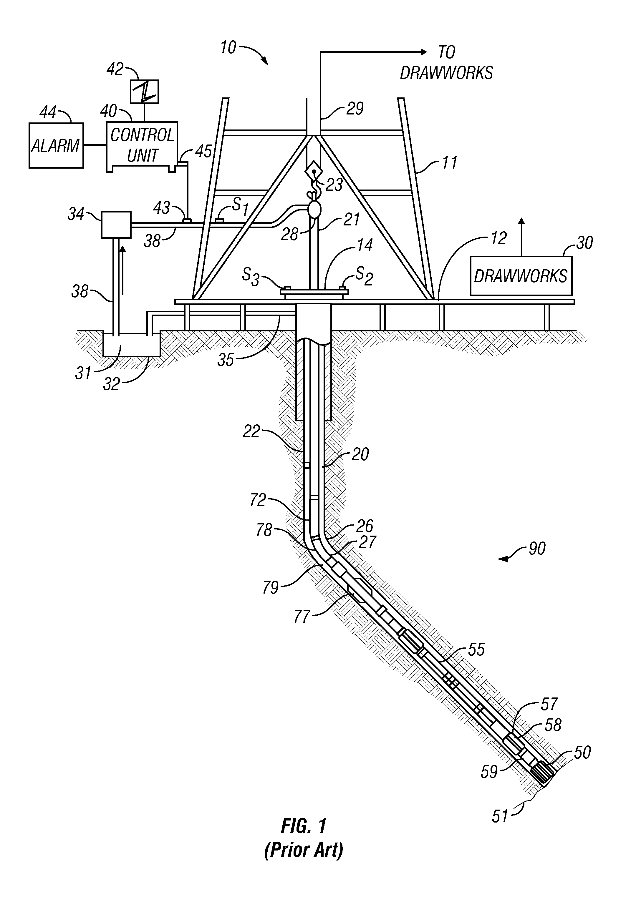
[0034]FIG. 1 shows a schematic diagram of a drilling system 10 with a drillstring 20 carrying a drilling assembly 90 (also referred to as the bottom hole assembly, or “BHA”) conveyed in a “wellbore” or “borehole”26 for drilling the wellbore. The drilling system 10 includes a conventional derrick 11 erected on a floor 12 which supports a rotary table 14 that is rotated by a prime mover such as an electric motor (not shown) at a desired rotational speed. The drillstring 20 includes a tubing such as a drill pipe 22 or a coiled-tubing extending downward from the surface into the borehole 26. The drillstring 20 is pushed into the wellbore 26 when a drill pipe 22 is used as the tubing. For coiled-tubing applications, a tubing injector, such as an injector (not shown), however, is used to move the tubing from a source thereof, such as a reel (not shown), to the wellbore 26. The drill bit 50 attached to the end of the drillstring breaks up the geological formations when it is rotated to dri...


PUM


Abstract

A galvanic resistivity tool with one or more measurement electrodes and guard electrodes, and one or more shielding electrodes. The potential difference between the measurement electrodes and the guard electrodes is controlled to minimize current flow between the measurement electrodes and the shielding electrodes. This provides improved focusing and avoids effects of contact impedance.

Description

BACKGROUND OF THE INVENTION[0001]1. Field of the Invention[0002]The present invention relates to well logging. In particular, the present invention is an apparatus and method for determining the resistivity of subsurface formations using electrical methods.[0003]2. Background of the Art[0004]In conventional galvanic resistivity measurement tools using a focusing technique, a guard electrode emits current in order to lead the current beam of a measurement electrode deeper into a conductive material. The resistivity of the material is determined by means of measurement electrode's voltage and current registration. The driving potential on guard and measurement electrode must be exactly the same to avoid disturbances of the ideal electrical field, which makes sure that the focusing effect takes place. Higher driving potential differences may lead to currents from guard to measurement electrode or vice versa passing the borehole fluid around the tool, which would completely destroy the ...

Claims


Application Information

Patent Timeline
Patent Type & Authority Patents(United States)
IPC IPC(8): G01V3/02G01V3/18
CPCG01V3/20
Inventor GOREK, MATTHIASFOLBERTH, MARTINFULDA, CHRISTIAN
Owner BAKER HUGHES INC
Why Eureka
Try Eureka