
Method of detecting longitudinal force of tire and longitudinal force detecting apparatus used therein

a technology of longitudinal force and detecting apparatus, which is applied in the direction of vehicle tyre testing, instruments, roads, etc., can solve the problems of difficult to sufficiently increase the measurement precision and the amount of time of shift, and achieve excellent computing precision, excellent processing speed, and easy execution

Inactive Publication Date: 2007-08-21
SUMITOMO RUBBER IND LTD +1
View PDF4 Cites 6 Cited by
  • Summary
  • Abstract
  • Description
  • Claims
  • Application Information

AI Technical Summary

Benefits of technology

The present invention provides a method and apparatus for detecting the longitudinal force of a tire. The method involves using a pair of sensors to detect the rotation angle of the axle and the position of a mark in the tire. These sensors provide information that is used to compute the longitudinal force of the tire using a previously determined relational equation. The apparatus includes a computing means that sequentially stores and uses the rotation angle information to compute the longitudinal force of the tire. The technical effect of this invention is to provide a simple and reliable method for detecting the longitudinal force of a tire, even in a flat tire, to improve steering stability.

Problems solved by technology

Further, since a distance in the radial direction between the magnetic bodies becomes small, a gain of the temporal shift amount is small, and since both the reference positions are affected by the warp deformation of the tire, it is hard to sufficiently increase a measuring precision.

Method used


Image

  • Method of detecting longitudinal force of tire and longitudinal force detecting apparatus used therein
  • Method of detecting longitudinal force of tire and longitudinal force detecting apparatus used therein
  • Method of detecting longitudinal force of tire and longitudinal force detecting apparatus used therein

Examples


example

[0074]By using the detecting method in accordance with the present invention, the longitudinal force applied to the tire was detected on the basis of the specification in Table 1, and a resolving power of the detection and an effectiveness to the vehicle control system such as ABS, TCS, ESC or the like are evaluated by four stages comprising x, Δ, ◯ and ⊚. In this case, the sign Δ means the same level as the performance in the current vehicle control system.

[0075]Further, the tire was attached to the vehicle and the vehicle was run actually, and the longitudinal force generated in the tire at that time was compared between a case that the longitudinal force was detected on the basis of the specification in the example 2, and a case that the longitudinal force was measured by using a six-component meter. The result of comparison is shown in FIGS. 6(A) and 6(B). FIG. 6A shows a case of slowly putting on the brake from a constant speed running state at a speed of 40 km / h, that is, a ca...


PUM


Abstract

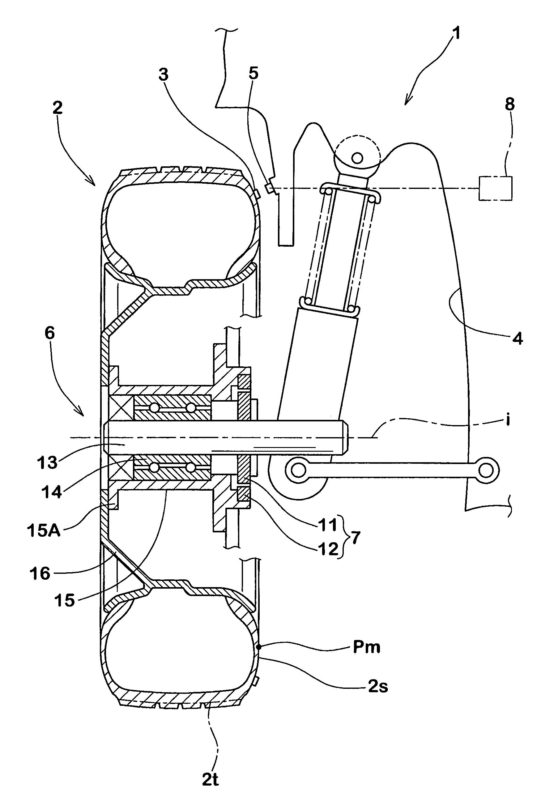
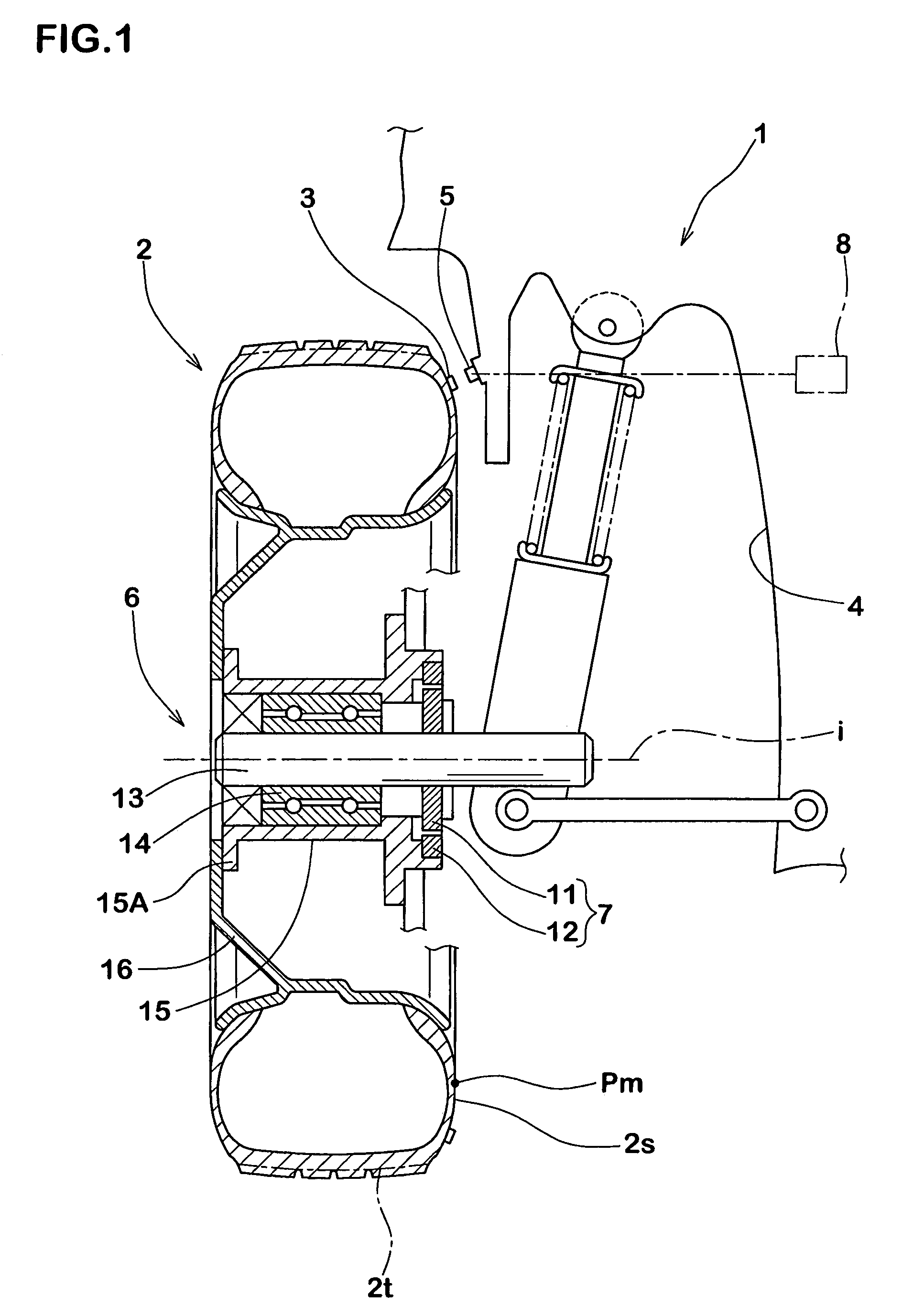
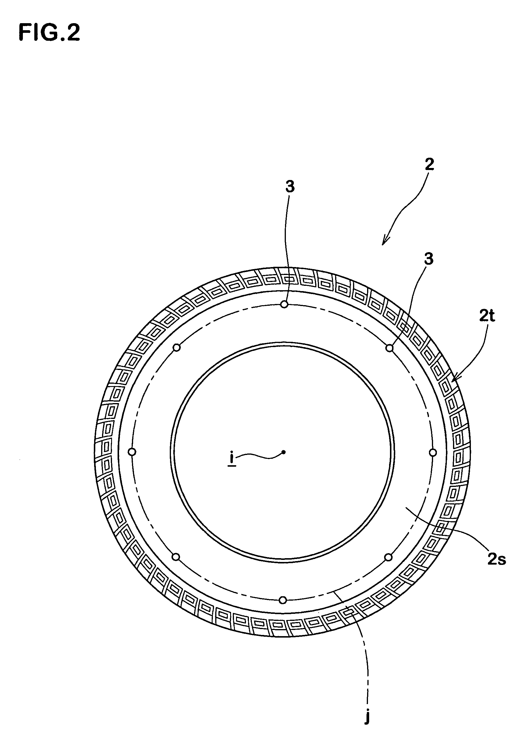
An apparatus for detecting a longitudinal force of a tire is provided with at least one mark (3) provided in on one circumferential line (j) in a tire (2), a first sensor (5) disposed in a vehicle body side (4) and capable of detecting a passage of the mark (3), a second sensor (7) capable of detecting a rotation angle (θ) of an axle (6), and a computing device (8) for computing a longitudinal force (Fr) of the tire (2) on the basis of an information of the first and second sensors (5, 7). The computing device (8) sequentially stores a rotation angle (θr) of the axle (6) when the mark (3) passes through the first sensor (5). Further, the computing device (8) computes a tire warp angle (αr) corresponding to a difference (θo−θr) between a no-load rotation angle θo (a rotation angle of the axle (6) in a no-load state) stored in advance and the rotation angle θr, and sequentially computes a tire longitudinal force (Fr) of a tire applied during the running from the warp angle (αr), using a previously determined relational equation F=f(α) between the warp angle (α) and the tire longitudinal force (F).

Description

BACKGROUND OF THE INVENTION[0001]1. Field of the Invention[0002]The present invention relates to a method of detecting a longitudinal force of a tire which can detect a longitudinal force (a force in a tire circumferential direction) applied to the tire at a high precision on the basis of a warp angle of the tire, can accurately comprehend a rolling condition of the tire, and can make a contribution to a control of a vehicle control system, and a longitudinal force detecting apparatus used therein.[0003]2. Description of the Related Art[0004]In recent years, in order to secure a stability and a safety of a running motor vehicle, there has been developed various vehicle control systems such as an antilock brake system (ABS), a traction control system (TCS), an electric stability control (ESC) and the like. Further, in order to control these systems, it is necessary to accurately comprehend a rolling condition of the running tire.[0005]For example, in the ABS, it is important to maint...

Claims


Application Information

Patent Timeline
Patent Type & Authority Patents(United States)
IPC IPC(8): G01M17/02
CPCB60T8/1725B60T8/52G01N19/02
Inventor MIYOSHI, AKIHIRONAKANO, KEITA
Owner SUMITOMO RUBBER IND LTD
Learn More