Method for verification of at least one given fuel mixture ratio

a fuel mixture and ratio technology, applied in the direction of liquid fuel feeders, relative volume flow measurements, liquid/fluent solid measurements, etc., can solve the problem of no longer being used as flushing fuel, and achieve the effect of preventing not only insufficient flushing, but also excessive throughput of diesel fuel

Inactive Publication Date: 2007-08-21
KANGLER WOLFRAM
View PDF4 Cites 10 Cited by
  • Summary
  • Abstract
  • Description
  • Claims
  • Application Information

AI Technical Summary

Benefits of technology

[0022]An essential aspect of the method according to the invention rests in the fact that with the supply of a second fuel type or with the change from the supply of the first fuel type to the second fuel type, the fuel volume conveyed by the injection system is determined and dependent on the determined fuel volume, the presence of a preset resp. given fuel mixture ratio is verified. The advantage of measuring the conveyed fuel volume is that this measured quantity makes it possible to determine exactly the mixture ratio of the fuel mixture in the injection system, independent of the current operating parameters. This prevents not only insufficient flushing, but also excessive throughput of the diesel fuel used for the flushing process. The latter is no longer unmixed after the flushing process and therefore can no longer be used as flushing fuel.
[0023]It is particularly advantageous that the fuel mixture ratios in the injection system can be adjusted as needed. This enables, in all operating conditions for example of a series production diesel engine, the complete combustion of the vegetable oil (mixed with diesel), especially since the mixture ratio can be set as high as 100% free of vegetable oil. Damage resulting from the use of pure vegetable oil in operating conditions not suitable for such use are prevented by the use of such a fuel mixture.

Problems solved by technology

The latter is no longer unmixed after the flushing process and therefore can no longer be used as flushing fuel.

Method used


Image

  • Method for verification of at least one given fuel mixture ratio
  • Method for verification of at least one given fuel mixture ratio

Examples


Embodiment Construction

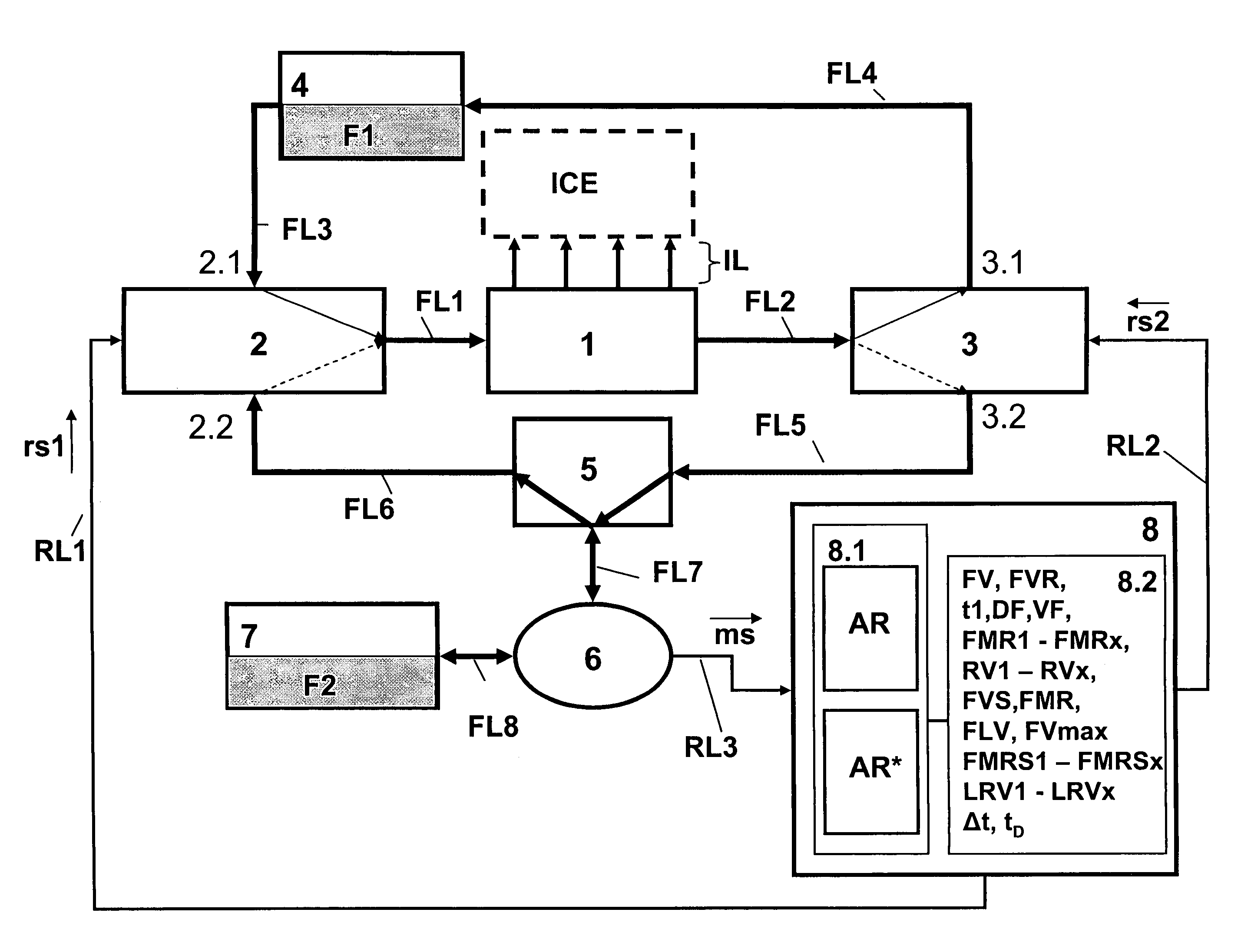
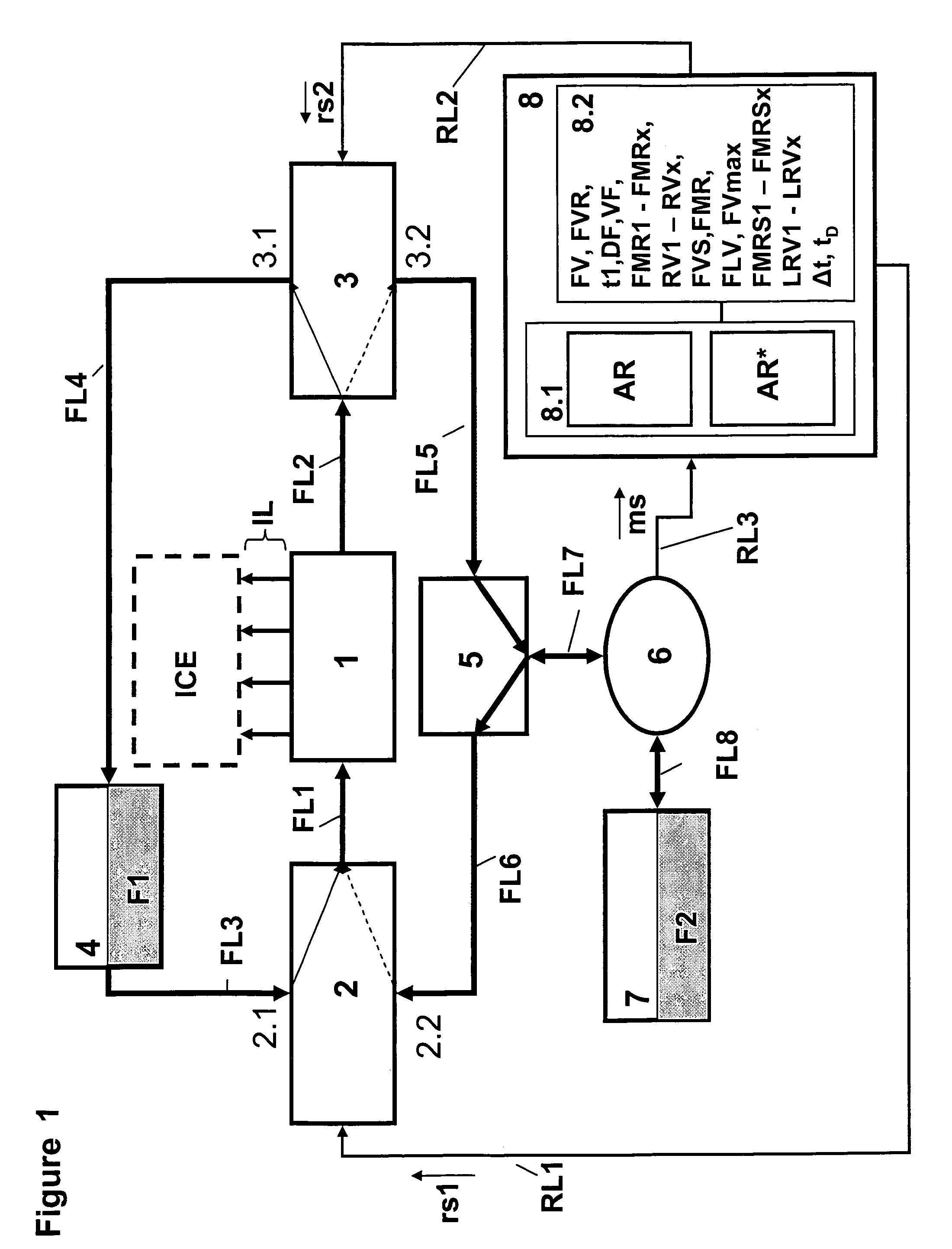
[0028]FIG. 1 shows by way of example in a schematic block diagram one injection system 1, which is connected via several injection lines IL for example to an internal combustion engine ICE, into which at least one fuel type F1, F2 or one fuel mixture is injected. The injection system 1 is connected via a first fuel line FL1 with a forward flow valve 2 and via a second fuel line FL2 with a return flow valve 3. By way of example the forward flow valve and the return flow valve 2, 3 are designed as 3 / 2 way valves, which preferably can be implemented as electrically actuated solenoid valves.

[0029]The forward flow valve 2 is connected via a third fuel line FL3 to a first fuel tank 4, which is filled with the first fuel F1. In the present embodiment, the first fuel tank 4 is filled with diesel fuel as the first fuel F1. The diesel fuel circuit is completed by connecting the return flow valve 3 via a fourth fuel line FL4 with the first fuel tank 4.

[0030]The line leading from the forward fl...


PUM


Abstract

A fuel injection system during operation of an internal combustion engine with at least two separately stored fuel types is supplied with at least one first fuel type. With the supply of a second fuel type or with the change from the supply of the first fuel type to the second fuel type, the fuel volume conveyed by the injection system is determined and dependent thereon the presence of a given fuel mixture ratio is verified.

Description

BACKGROUND OF THE INVENTION[0001]The present invention relates to a method for verification of at least one given fuel mixture ratio in a fuel injection system during operation of an internal combustion engine with at least two separately stored fuel types, wherein the injection system is supplied with at least one first fuel type.[0002]The use of vegetable oils as biomass fuels offers ecological and economical advantages as compared with fossil fuels. Vegetable oils are obtained from renewable raw materials, which mean that during combustion they are essentially carbon dioxide neutral, free of sulfur and, as opposed to conventional fuels, biologically degradable. Furthermore, the discharge of particles during combustion is reduced drastically in comparison with diesel.[0003]Due to the different chemical and physical fuel properties of vegetable oils as compared with diesel fuels or bio diesel, specially developed vegetable oil engines or modified series production diesel engines mu...

Claims


Application Information

Patent Timeline
Patent Type & Authority Patents(United States)
IPC IPC(8): F02M43/00
CPCF02D19/0628F02D41/0025F02M37/0064F02D19/0621F02D19/0652F02D19/0665F02D19/0678F02D19/081F02D41/064F02D2041/389F02D2200/0612F02D2200/0614F02M37/0088Y02T10/36Y02T10/30
Inventor KANGLER, WOLFRAM
Owner KANGLER WOLFRAM
Why Eureka
Try Eureka