Antenna control unit and phased-array antenna

a control unit and antenna technology, applied in the manufacture of antenna arrays, antennas, waveguides, etc., can solve the problems of reducing unable to obtain sufficient phase shift amount, and deteriorating the control of the antenna's directivity, so as to reduce the manufacturing cost, improve the directivity gain, and reduce the amount of beam tilt.

Inactive Publication Date: 2007-08-21
PANASONIC CORP
View PDF13 Cites 6 Cited by
  • Summary
  • Abstract
  • Description
  • Claims
  • Application Information

AI Technical Summary

Benefits of technology

[0029]Therefore, it is possible to obtain a low-cost phase shifter which provides an effective phase shift amount and is manufactured in few processes. Consequently, an antenna control unit can be manufactured in few processes, whereby the manufacturing cost of the antenna control unit can be reduced.
[0051]Therefore, a phased-array antenna that has a more pointed beam (larger directivity gain) as well as a more satisfactory beam tilt amount and that can implement X-axial and Y-axial beam tilt can be manufactured in fewer processes, thereby reducing the manufacturing cost.

Problems solved by technology

In addition, the amount of beam tilt is reduced, and as a result, the control of the antenna's directivity is deteriorated.
Consequently, as mentioned above, the power from the microstrip hybrid coupler 703 does not enter the microstrip stub 704 so efficiently, and thus, the sufficient phase shift amount cannot be obtained.
However, when the magnetic material is provided in proximity of the microstrip stub 704 of the phase shifter 700 to suppress the reduction in the matching degree of the line impedance Z between both the line sections 703 and 704, so as to obtain a larger phase shift amount, as in the above-mentioned Prior Art 1, there arises an additional problem in that more processes are needed when the phase shifter 700 is produced by firing.
As a result, the manufacturing cost of the phase shifter is adversely increased.

Method used


Image

  • Antenna control unit and phased-array antenna
  • Antenna control unit and phased-array antenna
  • Antenna control unit and phased-array antenna

Examples


first embodiment

[0062]Hereinafter, a first embodiment of the present invention will be described with reference to FIGS. 1(a) and 1(b).

[0063]In the first embodiment, a phase shifter that is employed for a phased-array antenna of the present invention will be described.

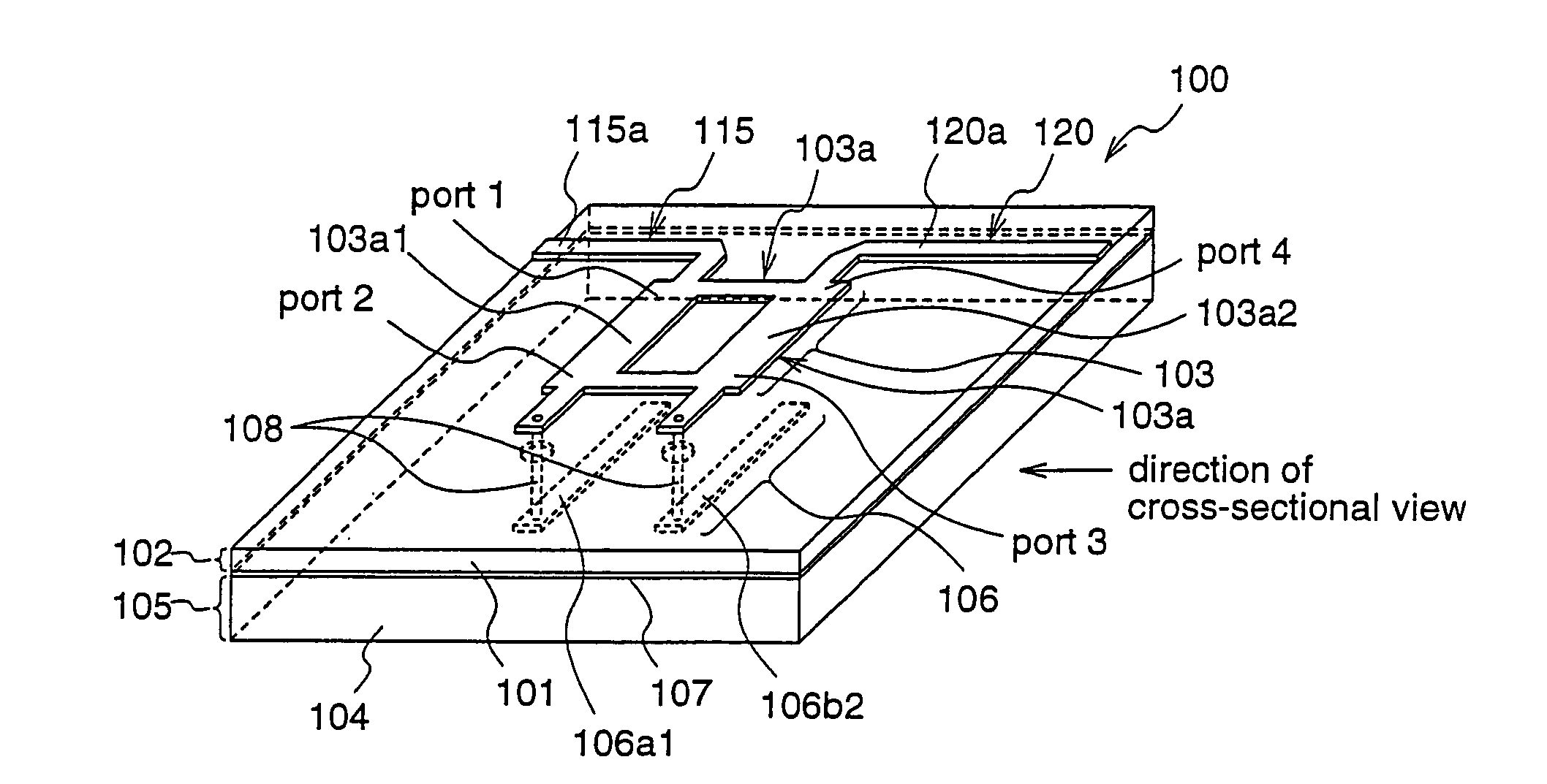
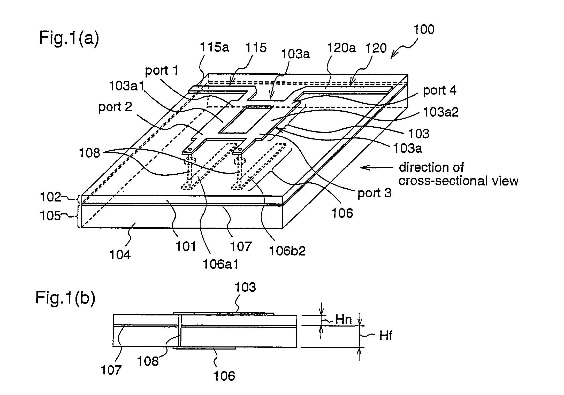
[0064]FIG. 1(a) is a perspective view and FIG. 1(b) is a cross-sectional view illustrating a construction of the phase shifter according to the first embodiment, which is employed for the phased-array antenna of the present invention.

[0065]In FIGS. 1(a) and 1(b), reference numeral 100 denotes a phase shifter. Reference numeral 101 denotes a paraelectric base material, reference numeral 102 denotes a paraelectric transmission line layer, reference numeral 103 denotes a microstrip hybrid coupler, reference numeral 104 denotes a ferroelectric base material, reference numeral 105 denotes a ferroelectric transmission line layer, reference numeral 106 denotes a microstrip stub, reference numeral 107 denotes a ground conductor, and reference...

second embodiment

[0080]A second embodiment of the present invention will be described with reference to FIGS. 2(a) and 2(b).

[0081]In this second embodiment, a phase shifter that is employed for a phased-array antenna of the present invention will be described.

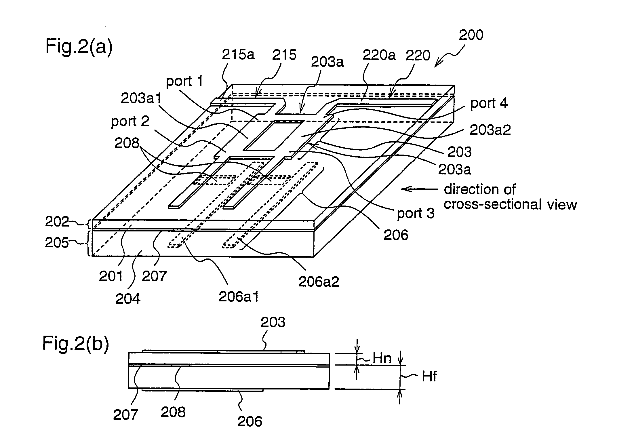
[0082]FIG. 2(a) is a perspective view and FIG. 2(b) is a cross-sectional view illustrating a construction of the phase shifter according to the second embodiment, which is employed for the phased-array antenna of the present invention.

[0083]In FIGS. 2(a) and 2(b), reference numeral 200 denotes a phase shifter. Reference numeral 201 denotes a paraelectric base material, reference numeral 202 denotes a paraelectric transmission line layer, reference numeral 203 denotes a microstrip hybrid coupler, reference numeral 204 denotes a ferroelectric base material, reference numeral 205 denotes a ferroelectric transmission line layer, reference numeral 206 denotes a microstrip stub, reference numeral 207 denotes a ground conductor, and reference numeral ...

third embodiment

[0098]A third embodiment of the present invention will be described with reference to FIGS. 3(a) and 3(b).

[0099]FIG. 3(a) is a diagram illustrating a construction of a phased-array antenna according to the third embodiment, and FIG. 3(b) is a diagram showing directivities of the phased-array antenna according to the third embodiment in a case where a beam tilt voltage is applied and a case where a beam tilt voltage is not applied.

[0100]In FIG. 3(a), a phased-array antenna 330 according to the third embodiment comprises an antenna control unit 300, a beam tilt voltage 320 for performing control of the directivity (beam tilt) as shown in FIG. 3(b), and four antenna elements 310a-310d. The antenna control unit 300 comprises an input terminal (feeding terminal) 301, four antenna terminals 307a-307d, four phase shifters 308a1-308a4, four loss elements 309a1-309a4, a high frequency blocking element 311, a DC blocking element 312, a transmission line (feeding line) 302 from the input termi...


PUM


Abstract

A paraelectric transmission line layer and a ferroelectric transmission line layer are laminated through a ground conductor, and plural phase shifters, which are connected via through holes that pass through the ground conductor, are disposed on both of the transmission line layers at some positions on a feeding line that branches off from the input terminal between all antenna terminals and an input terminal to which a high-frequency power is applied. In addition, loss elements each having the same transmission loss amount as the phase shifter, or the phase shifters are disposed so that transmission loss amounts from all of the antenna terminals to the input terminal are equalized. Accordingly, an antenna control unit which can be manufactured in fewer manufacturing processes and has a pointed beam and a large beam tilt amount, and a phased-array antenna that employs such an antenna control unit are provided.

Description

TECHNICAL FIELD[0001]The present invention relates to an antenna control unit that employs a ferroelectric as a phase shifter, and a phased-array antenna that utilizes such an antenna control unit. More particularly, the present invention relates to an antenna control unit such as mobile unit identifying radio or automobile collision avoidance radar, and a phased-array antenna that utilizes such an antenna control unit.BACKGROUND ART[0002]Systems such as “Active phased-array antenna and antenna control unit” described in Japanese Published Patent Application No. 2000-236207 (hereinafter, referred to as Prior Art 1) have been suggested as examples of conventional phased-array antennas that employ a ferroelectric as a phase shifter.[0003]Hereinafter, a conventional phased-array antenna will be described with reference to FIGS. 9 and 10.[0004]Initially, operating principles of a conventional phase shifter are described with reference to FIGS. 9(a) and 9(b). FIGS. 9(a) and 9(b) are diag...

Claims


Application Information

Patent Timeline
Patent Type & Authority Patents(United States)
IPC IPC(8): H01P5/12H01P9/00H01Q21/00H01P1/18H01Q3/26H01Q3/36
CPCH01P1/181H01Q3/26H01Q21/0087H01Q21/0006H01Q21/0075H01Q3/36H01P1/18
Inventor KIRINO, HIDEKI
Owner PANASONIC CORP
Why Eureka
Try Eureka