Sensorless fuel level and oil change indicators

a sensorless, fuel level indicator technology, applied in the direction of batteries/cells, process and machine control, instruments, etc., can solve the problems of complex indicators, inaccurate fuel level values measured by fuel level sensors, and high cos

Inactive Publication Date: 2007-08-21
BLUWAV SYST LLC
View PDF9 Cites 37 Cited by
  • Summary
  • Abstract
  • Description
  • Claims
  • Application Information

AI Technical Summary

Benefits of technology

[0009]In particular, the input power of the engine may be calculated as a ratio of the output power and the engine efficiency determined for a particular combination of engine temperature and engine speed. The output powe

Problems solved by technology

However, in a moving vehicle, fuel level values measured by fuel level sensors may be inaccurate due to driving conditions, such as accelera

Method used


Image

  • Sensorless fuel level and oil change indicators
  • Sensorless fuel level and oil change indicators
  • Sensorless fuel level and oil change indicators

Examples


Embodiment Construction

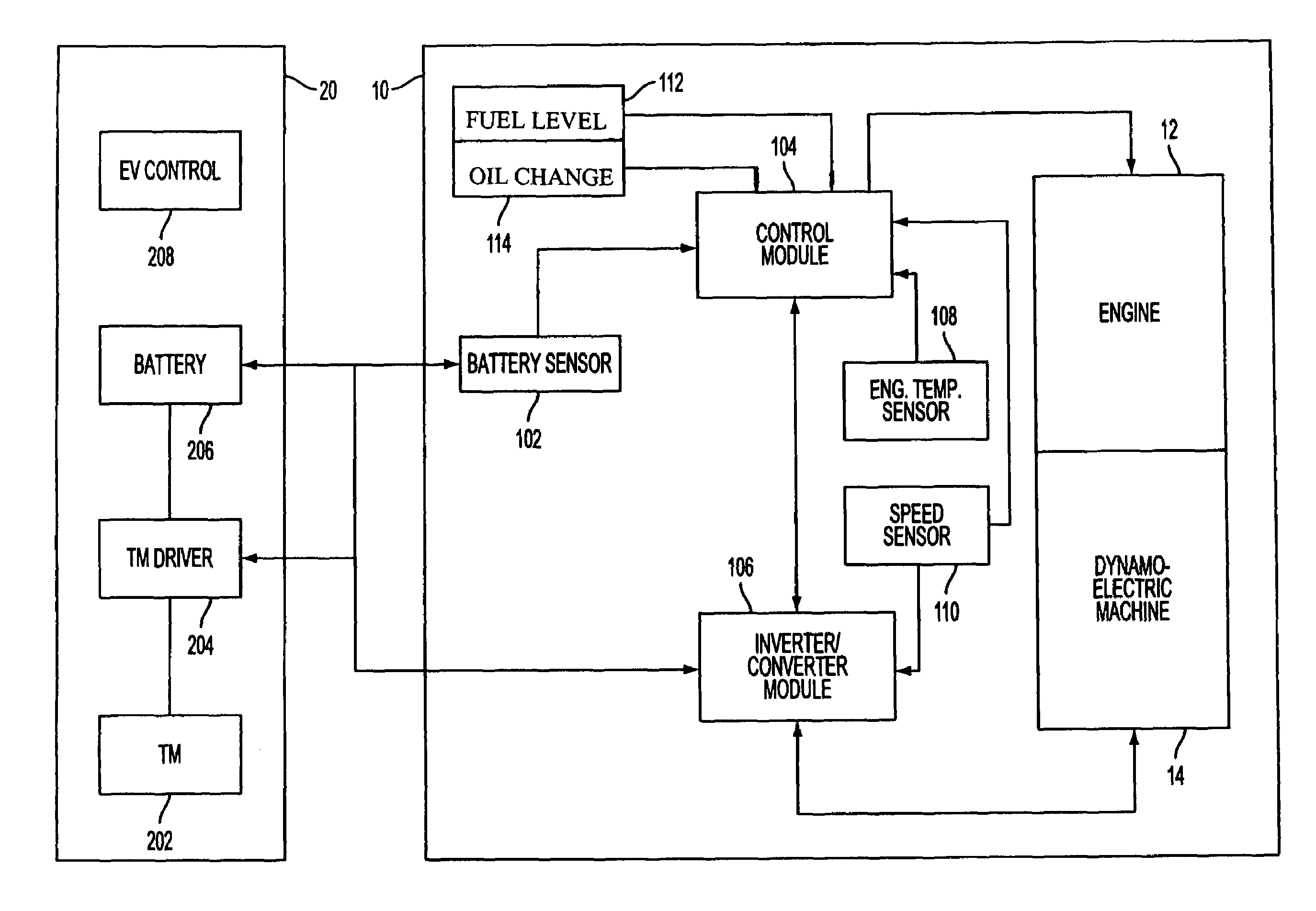
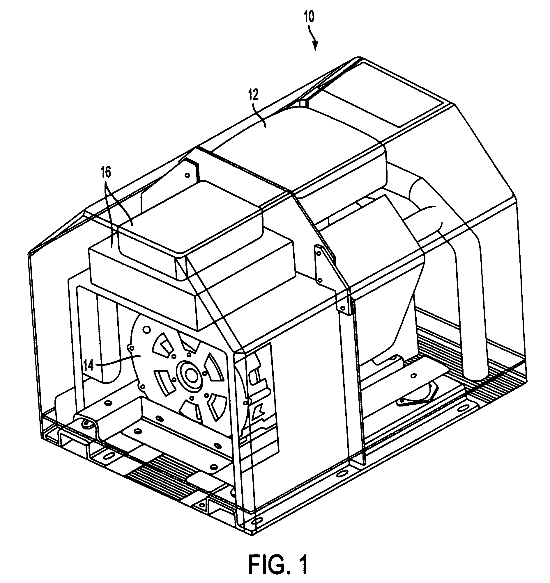
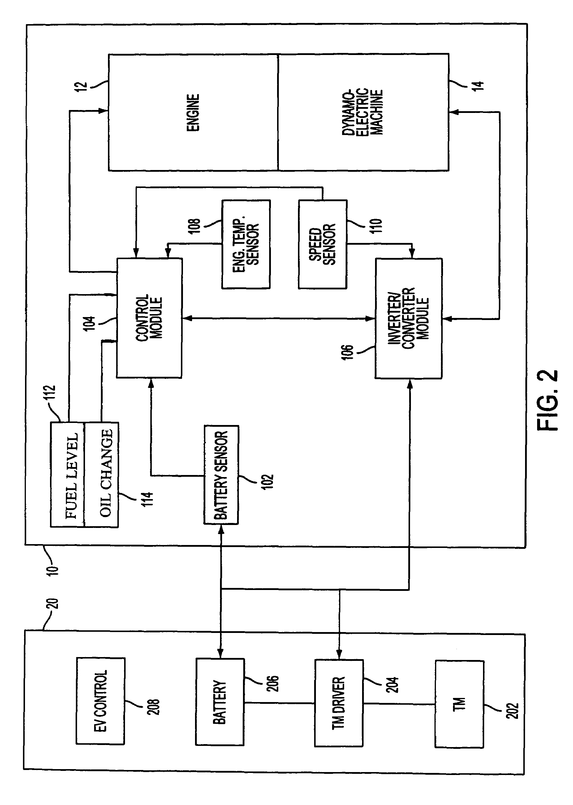
[0022]FIG. 1 illustrates a range extender 10, in which sensorless fuel level and oil change indicators of the present invention may be advantageously employed. The range extender 10 comprises a prime mover 12, such as an internal combustion engine, a dynamoelectric machine 14 coupled to the prime mover 12 by a hollow shaft of the dynamoelectric machine 14, and an electronic control system 16 for controlling operations of the prime mover 12 and the dynamoelectric machine 14. The dynamoelectric machine 14 is controlled to operate as a motor for starting the engine 12 when the engine 12 is turned on. When prescribed engine conditions are detected, the control system 16 controls the dynamoelectric machine 14 to operate as an electric generator driven by the engine 12 to produce electric power supplied to an external load, such as an all-electric vehicle. The dynamoelectric machine 14 may be a 3-phase AC electric machine including a stator with a shaft, a rotor and a housing. A fuel cont...


PUM


Abstract

Sensorless fuel level and oil change indicators are provided in a range extender for an electric vehicle. The range extender includes an engine, and an electric generating device driven by the engine to generate electric power supplied to the vehicle. The fuel level is calculated based on the generated power. The oil change indicator indicates that the oil should be changed when the number of engine rotor revolutions exceeds a threshold value. The electric generating device may be a dynamoelectric machine coupled to the engine by a shaft to operate as a motor for starting the engine. In response to prescribed engine conditions, the dynamoelectric machine is switched to operate as a generator driven by the engine to generate the electric energy.

Description

FIELD OF THE INVENTION[0001]The present invention relates to maintenance indicators for determining a fuel level and when engine oil should be changed in motor vehicles, and, more particularly, to indication of fuel level and oil change without sensors that detect a level of fuel and engine oil condition.BACKGROUND ART[0002]Traditionally, maintenance indicators in a vehicle utilize sensors for indicating operating parameters relating to materials required to operate the engine. For example, a fuel level in automobile fuel tanks is determined using a fuel level sensor having an elongated rod with a free end supporting a float which moves along with changes in fuel levels. The other end of the rod is pivotally mounted to an indicating mechanism typically including an elongated electrical resistance grid and a contact pad which moves with movements of the float and the rod as the fuel level changes. The movement of the contact pad along the resistance grid changes electrical characteri...

Claims


Application Information

Patent Timeline
IPC IPC(8): B60Q1/00
CPCB60L11/126G01F23/00B60L11/123B60W50/14B60W2560/02Y02T10/6217Y02T10/7005Y02T10/7077B60L2200/18B60L2200/28B60L50/61B60L50/62B60W2530/209Y02T10/62Y02T10/70Y02T10/7072
Inventor CHO, CHAHEE PETERKIM, EUN SHIK
Owner BLUWAV SYST LLC
Why Eureka
Try Eureka