Unique space time adaptive system (USS)

a space time adaptive system and unique technology, applied in the field of radars, can solve the problems of reducing the effect and utilizing many channels, and achieve the effect of accurately determining the range, velocity and azimuth of the obj

Inactive Publication Date: 2007-08-21
CATALDO THOMAS J
View PDF21 Cites 61 Cited by
  • Summary
  • Abstract
  • Description
  • Claims
  • Application Information

AI Technical Summary

Benefits of technology

[0012]USS does not require clutter cancellation therefore there is no clutter covariance matrix or training data involved or knowledge aided information. Channel matching is not required. USS has the ability to handle more returns than clutter and target per range doppler bin (RDB) or range azimuth bin (RAZ) and determine there ran...

Problems solved by technology

1—Channel matching is a problem but ...

Method used


Image

  • Unique space time adaptive system (USS)
  • Unique space time adaptive system (USS)
  • Unique space time adaptive system (USS)

Examples


Embodiment Construction

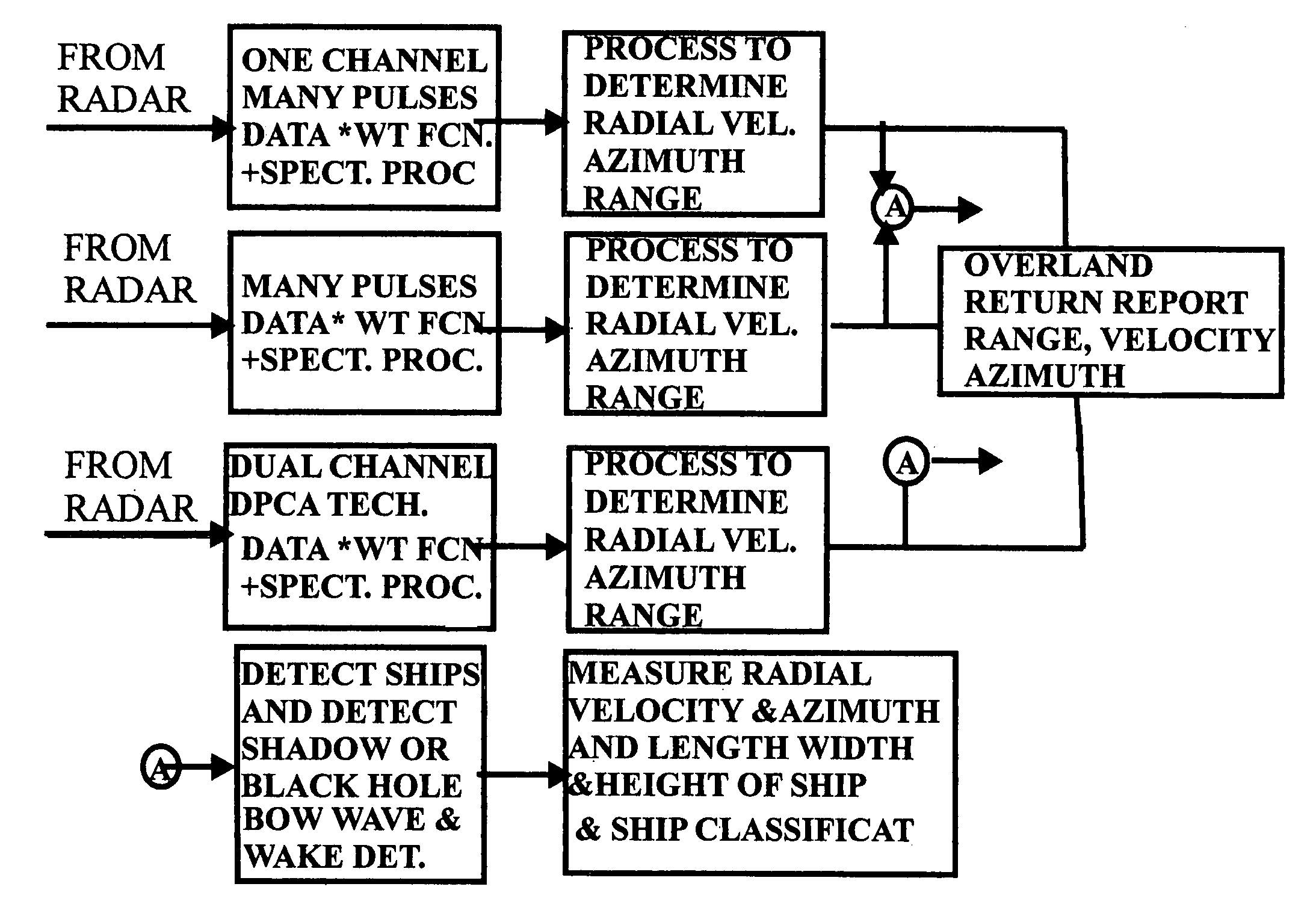
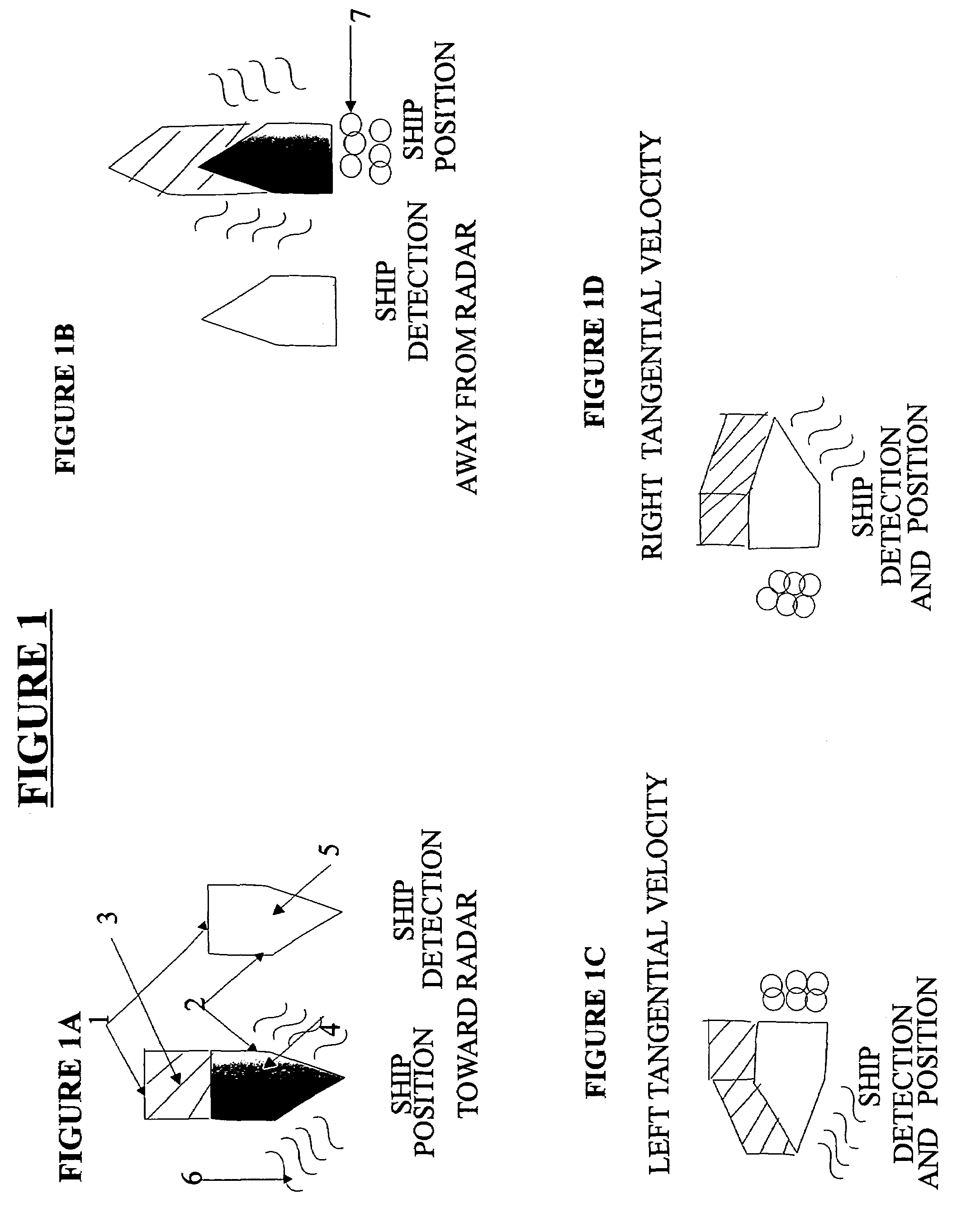
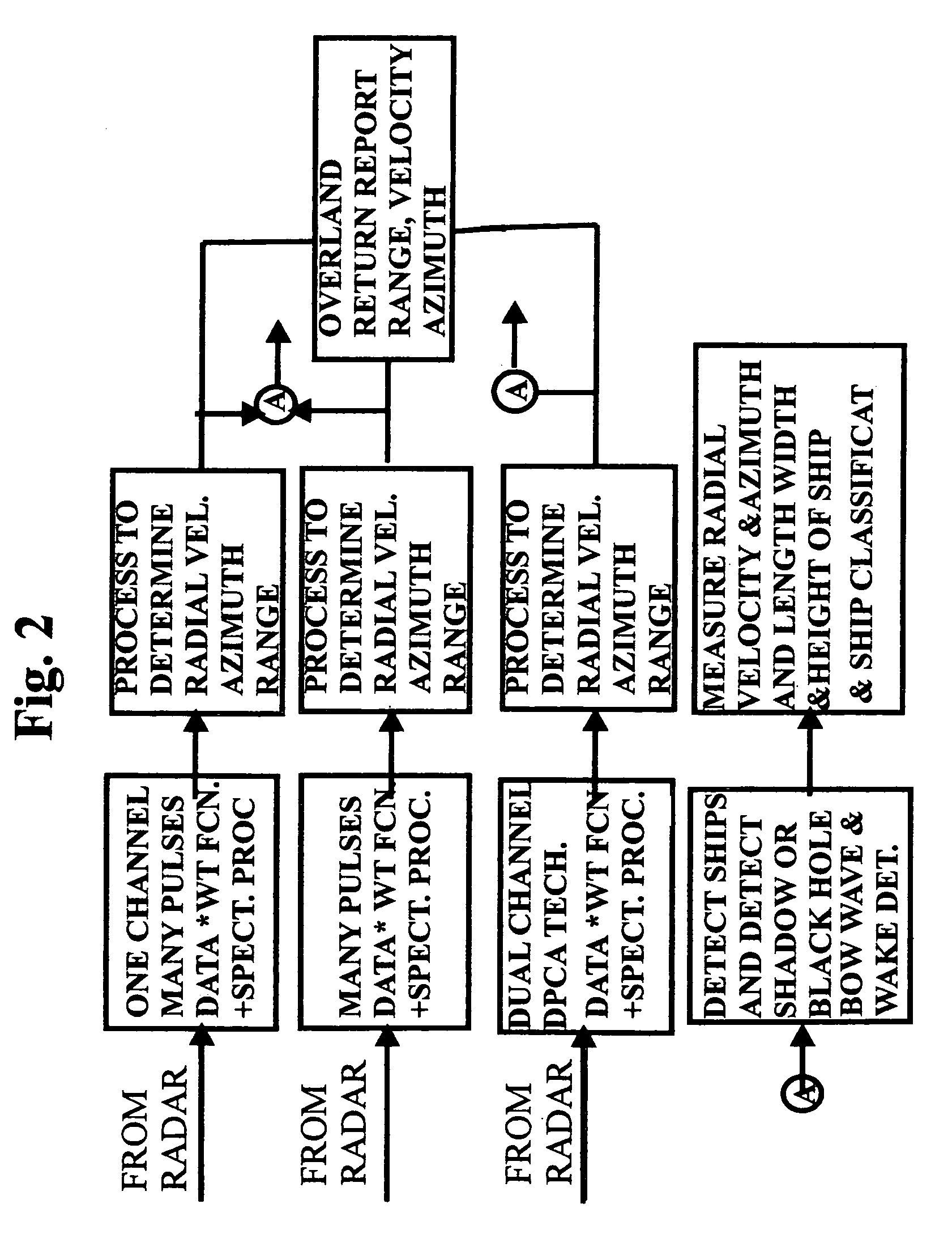
I. A—Basic Concept of a Unique Space Time Adaptive Radar System (USS)

[0032]It is to be noted that the description of this disclosure are illustrative and cannot show all possible implementations that may be employed from the information in the disclosure by a person of ordinary skill in the state of the art. Therefore this disclosure is illustrative and not limited of the scope of the proposed invention and not limited in the scope of the role in obtaining the objective of this disclosure.

[0033]USS processing system is applicable to all frequencies. The system is able to utilize all radio frequencies limited on the low end by the size of the antenna and on the high end by the practical limitations of short waves.

Illustrated in the patent application is a one dimensional array. The implementation may also be with two dimensional arrays as well.

II. B Basic Operations, Equations and Methodology Fundamental to all of the Systems Employed in this Disclosure

[0034]A—Fundamental Techniques ...


PUM


Abstract

A method of detecting radar returns and measuring their parameters with or without clutter present and no clutter cancellation employed which includes transmitting at least one pulse; processing the returns surpassing a threshold detected in one range azimuth bin and by processing and separating out the returns based on their different range and azimuth. Another method includes transmission of many pulses and has minimum of one channel return surpassing detected threshold, which is detected in one range Doppler bin. The method also includes processing and thereby separating out the returns based on their different radial velocity and or azimuth and comparing the returns to a database of expected returns and adaptively processing returns that do not correspond to the expected returns. The method identifies the non-corresponding returns as indicative of at least one of clutter, land sea interface, clutter discretes and antenna sidelobe returns each without utilizing clutter cancellation.

Description

CROSS REFERENCE TO RELATED APPLICATIONS[0001]This application claims the benefit, Under 35 U.S.C. § 119(e), of U.S. Provisional Application No. 60 / 677,576, filed May 4, 2005, which is hereby incorporated by reference.BACKGROUND OF THE INVENTION[0002]1. Field of Invention[0003]The field of the invention relates generally to radars and more specifically to a radar mounted on a moving platform employing an electronic scanned array with a transmission array and receive array (channel) or arrays (channels).[0004]2. Description of the Related Art[0005]In the field of this invention, detecting radar returns as moving targets and rejecting others such as clutter and others has been a challenge for many years. Obtaining a moving object's velocity, azimuth, and measurement of its parameters have been an objective of many radar systems. In relatively recent years with the increased processing and storage of improved integrated circuits, space time adaptive processing (“STAP”) has become more p...

Claims


Application Information

Patent Timeline
IPC IPC(8): G01S7/487G01S7/483G01S13/00G01S13/52
CPCG01S13/22G01S13/5246G01S2013/0254G01S2013/9064G01S13/9064
Inventor CATALDO, THOMAS J.
Owner CATALDO THOMAS J
Why Eureka
Try Eureka