Methods for automated uniformity assessment and modification of image non-uniformities

a technology of uniformity assessment and image, applied in the direction of optical radiation measurement, instruments, spectrometry/spectrophotometry/monochromators, etc., can solve the problems of specific non-uniformity and/or variation values, copier elements need correction, etc., and achieve the effect of reducing or eliminating errors

Inactive Publication Date: 2007-08-21
XEROX CORP
View PDF16 Cites 14 Cited by
  • Summary
  • Abstract
  • Description
  • Claims
  • Application Information

AI Technical Summary

Benefits of technology

[0032]Because many marking machines complete an image scan cycle in a few seconds, the use of spectrophotometers to provide image non-uniformity and / or variation information enables rapid feedback to field service personnel, which may shorten time to repair, increase up time, and provide a competitive advantage for image quality analysis systems with this capability.
[0038]The systems and methods according to the present invention quantify image non-uniformity and or variation characteristics so that marking machine errors can be diagnosed, the source of those errors identified, and service procedures performed in a user's environment in an expeditious manner to reduce or eliminate the errors. If, for example, the marking machine uses digital imaging technology, the resultant printed image can then be made a visually smooth and uniform halftone covering a specific area without noticeable streaks, bands, mottle or other visual image non-uniformities.

Problems solved by technology

Furthermore, specific non-uniformity and / or variation values may be a telltale sign that printer or copier elements needs correction.

Method used


Image

  • Methods for automated uniformity assessment and modification of image non-uniformities
  • Methods for automated uniformity assessment and modification of image non-uniformities
  • Methods for automated uniformity assessment and modification of image non-uniformities

Examples


Embodiment Construction

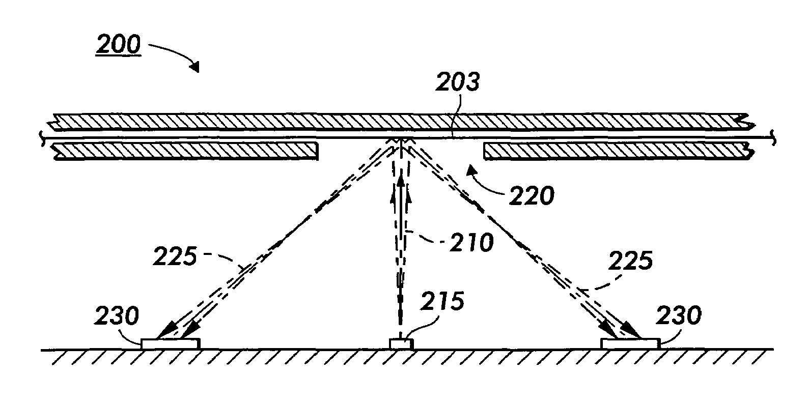
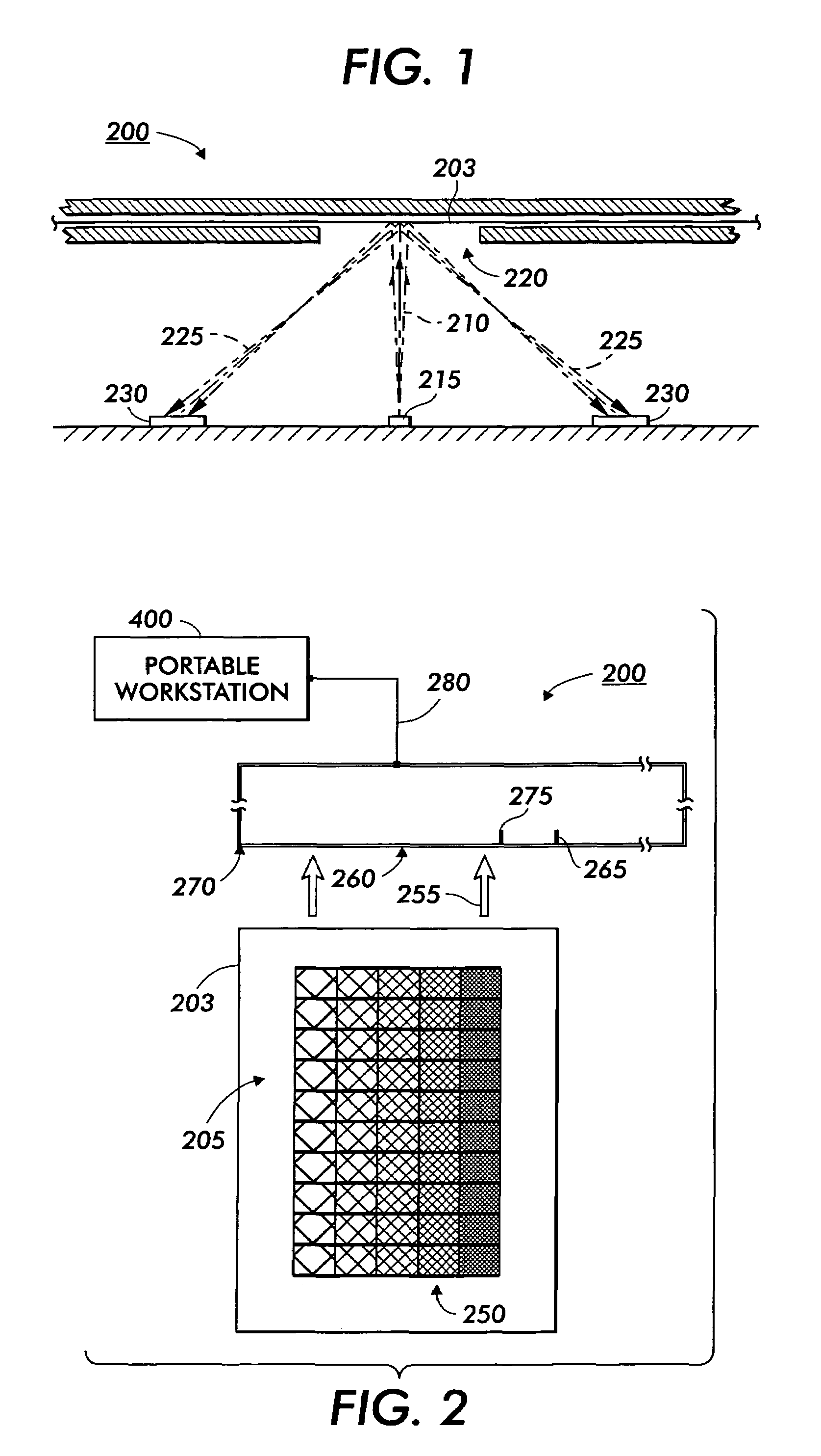
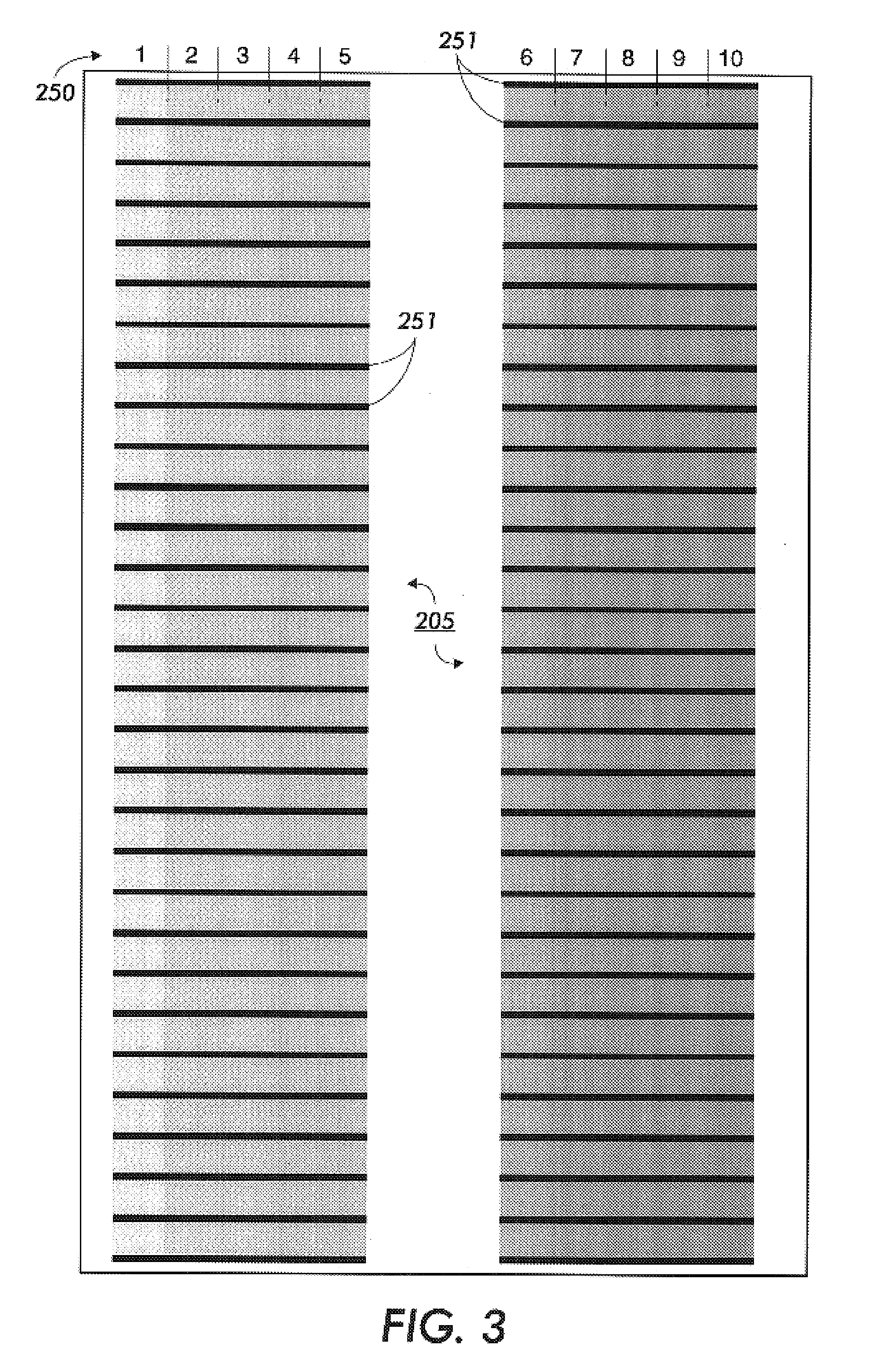
[0053]The following detailed description of various exemplary embodiments of reference strip scanning systems capable of providing reflectance as a function of position according to this invention may refer to one type of reference strip scanning system or image measurement device, such as a portable X-Rite® DTP41 spectrophotometer, or one type of substrate to be scanned, such as a sheet. However, it should be appreciated that the principles of this invention as outlined and / or discussed below, can be equally applied to any known or later developed image scanning system or device capable of providing transmission and / or reflectance as a function of position, and any known or later developed substrate, beyond the systems specifically discussed herein.

[0054]For simplicity and clarification, the operating principles and design factors of various exemplary embodiments of the systems and methods according to this invention are explained with reference to an exemplary embodiment of a spec...


PUM

PropertyMeasurementUnit
wavelength rangeaaaaaaaaaa
optical densityaaaaaaaaaa
color measuringaaaaaaaaaa

Abstract

Methods for automated uniformity assessment and modification of image non-uniformities using an image measurement device capable of determining image reflectance and / or transmitter as a function of position, such as a spectrophotometer, a calorimeter, and / or a densitometer. One or more of these devices scan an image on a substrate, such as a sheet, thereby generating data representing image characteristics, such as, for example, image non-uniformity. The sheet may contain a reference / test pattern including one column, strip or patch intended to have a uniform density. This data generated by the device after the scan of the substrate is analyzed with signal processing algorithms for image characteristics assessment, including image spatial uniformity and compared to reference image characteristics including image spatial uniformity. An image modification profile may be generated to be applied to a marking system to thereby alter subsequent image data and improve image spatial uniformity of the marking system.

Description

BACKGROUND OF THE INVENTION[0001]1. Field of Invention[0002]This invention relates to determining image characteristics.[0003]2. Description of Related Art[0004]In conventional marking systems, such as, for example, a laser printer, inkjet printer, or copier, one technique for monitoring the quality of prints is to create one or more “reference” or “test” patches of pre-determined desired tint. The reference / tint of a test patch may be referred to as the call or the density of the reference / test patch. The actual density of the material (often ink and / or toner) in each test patch can then be measured to determine the effectiveness of the printing process on marking a medium, such as for example, a sheet or reference strip. The uniformity of the image on the reference strip can then be determined.[0005]There are many methods known in the art whereby reference / test patches may be used to monitor the quality of prints. For instance, U.S. Pat. No. 6,639,669 B2 to Hubble, the disclosure ...

Claims


Application Information

Patent Timeline
Patent Type & Authority Patents(United States)
IPC IPC(8): G01N21/57G01N21/59H04N1/00H04N1/401
CPCH04N1/00058H04N1/4015H04N1/00002H04N1/00015H04N1/00031H04N1/00045H04N2201/0096
Inventor BUTTERFIELD, PAUL M.HANCOCK, JOSEPH D.ROOF, JR., NORMAN L.UPDEGRAFF, SHAWN P.
Owner XEROX CORP
Why Eureka
Try Eureka