

Remote power configuration of functions within multifunction apparatus using status and setting screens displayed on external apparatus
- Summary
- Abstract
- Description
- Claims
- Application Information
AI Technical Summary
Benefits of technology
Problems solved by technology
Method used
Image

Examples
first embodiment
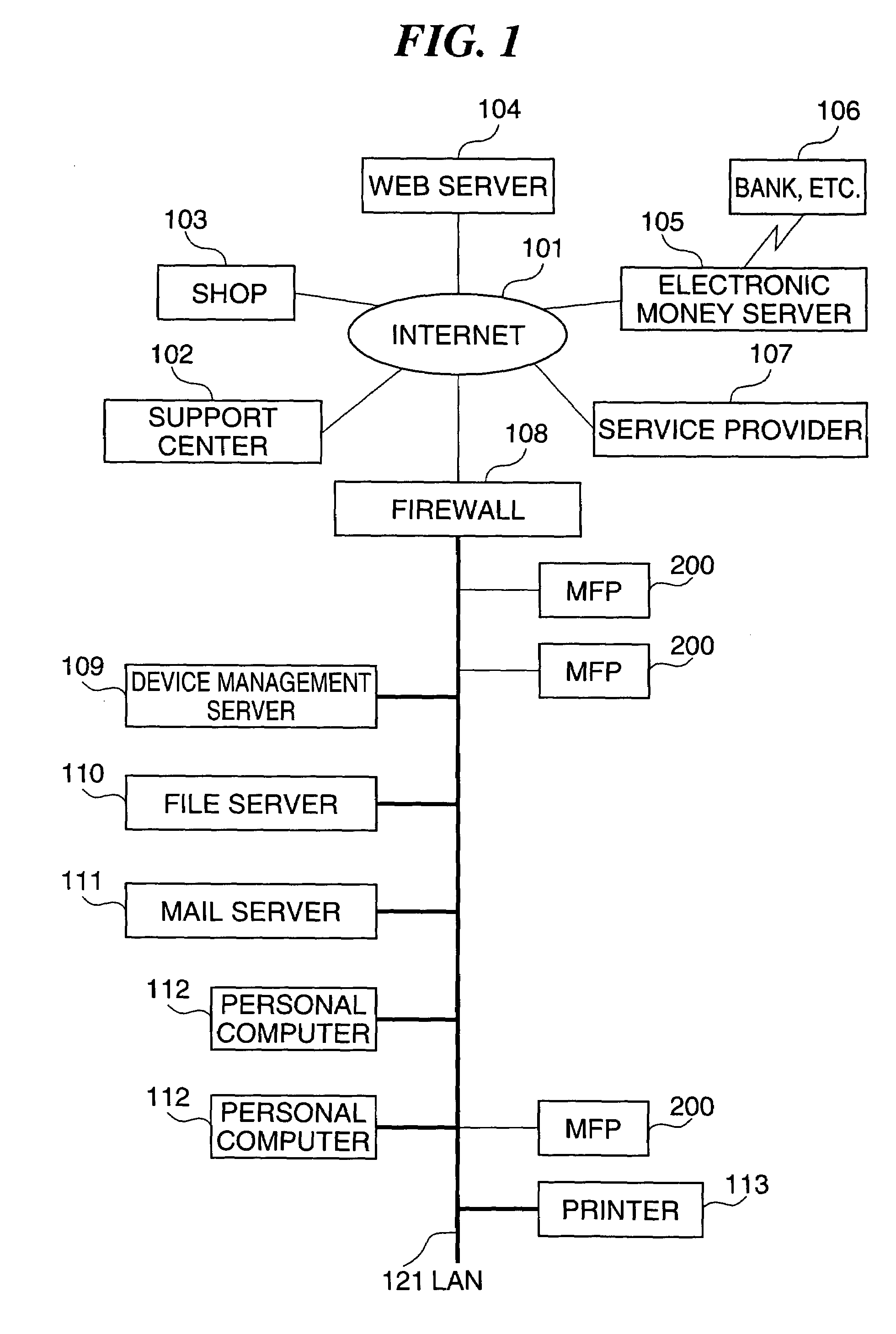
[0057]FIG. 1 is a diagram showing the arrangement of a remote control system incorporating an information processing apparatus according to the present invention. In FIG. 1, reference numeral 101 denotes a communication network such as the Internet; 102, a support center for providing support for hardware and software; 103, a hardware / software shop; 104, a Web server that is connected to the Internet to provide specific services for Internet users; 105, an electronic money server that deals with e.g. settlement between a banking institution 106 and clients (terminal apparatuses); and 107, a service provider that connects personal user's terminal apparatuses and the Internet 101 to each other.
[0058]It should be noted that clients as terminal apparatuses are implemented by personal computers 112, and are each comprised of a CPU (Central Processing Unit), non-volatile storage such as a RAM and a hard disk, an input / output section for inputting / outputting information to and from a varie...
second embodiment
[0088]A description will now be given of the present invention with reference to FIGS. 13 to 17 as well as FIGS. 10 to 12, referred to above.
[0089]The second embodiment is applied to a remote control system which is capable of performing on / off control of power supply, timer setting for setting / release of the sleep state, and display of the set period of time. The arrangement of the remote control system according to the present embodiment is identical with that of the above described first embodiment, and hence description thereof is omitted. Also, parts and elements corresponding to those of the first embodiment are designated by identical reference numerals, and hence description thereof is omitted.
[0090]The operative status of the sleeping MFP 200 can be viewed on the Web as shown in FIG. 10. It is possible to set the timer to release the MFP 200 from the sleep state at a desired time.
[0091]When the device button 403 is depressed, it is highlighted, and a sub menu is displayed (...
third embodiment
[0099]A description will now be given of the present invention with reference to FIGS. 18 to 25.
[0100]The third embodiment is applied to a remote control system which is capable of performing on / off control of power supply, and timer setting for setting / release of the sleep state. The arrangement of the remote control system is identical with that of the above described first embodiment, and hence description thereof is omitted. Also, parts and elements corresponding to those of the above described first embodiment are designated by identical reference numerals, and hence description thereof is omitted.
[0101]FIG. 18 is a view showing a window screen displayed for changing the display mode.
[0102]When the specification setting button 407 in FIG. 18 is selected, a menu of basic setting, network setting, and so forth is displayed. When display setting 1801 is selected from the menu, a device display button 1802 and a function display button 1803 are displayed. FIG. 18 shows a window scr...
PUM
 Abstract
Description
Claims
Application Information