Methods for optimizing turbine engine shell radial clearances

a technology of turbine engine shell and radial clearance, which is applied in the direction of machines/engines, liquid fuel engines, manufacturing tools, etc., can solve the problems of difficult control of such clearances, adversely affecting the performance of the associated turbomachinery, and time-consuming process for direct machining of such components

Active Publication Date: 2007-08-28
GENERAL ELECTRIC CO
View PDF16 Cites 36 Cited by
  • Summary
  • Abstract
  • Description
  • Claims
  • Application Information

AI Technical Summary

Problems solved by technology

Inadequate clearances defined within the turbine engincs, such as, but not limited to clearances between rotating seals and stationary members, between bearing elements and bearing races, between a bearing race and a damper housing, and / or between rotor blades and surrounding casing, may adversely affect performance of the associated turbomachinery.
Howevcr, maintaining control of such clearances may be difficult during engine operation as the second members may expcrience distortions which may alter the clearances defined betwcen the casings and second member.
However, direct machining such components may be a time consuming process that may be repeated several times until the critical bore shape is obtained.

Method used


Image

  • Methods for optimizing turbine engine shell radial clearances
  • Methods for optimizing turbine engine shell radial clearances
  • Methods for optimizing turbine engine shell radial clearances

Examples


Embodiment Construction

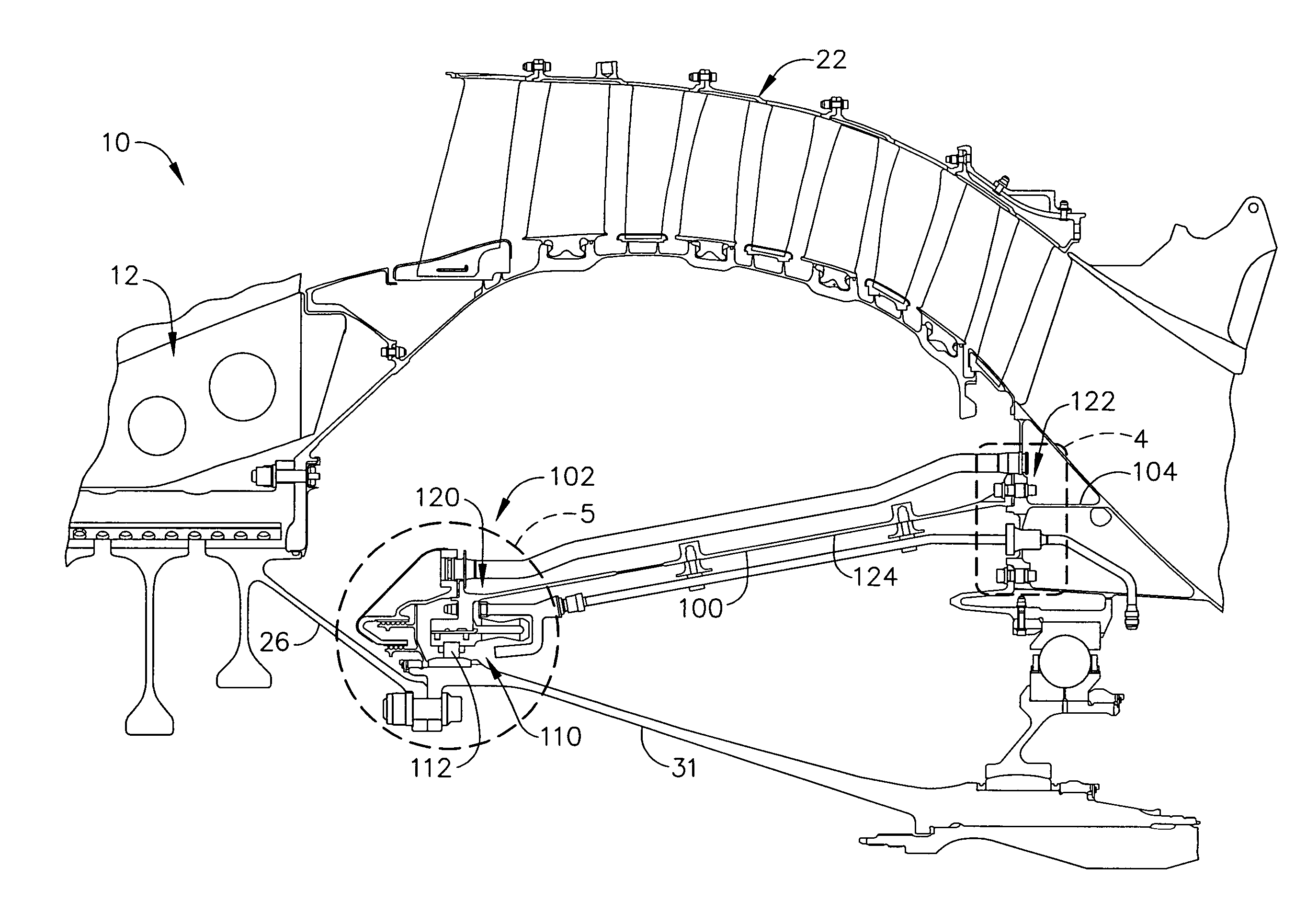
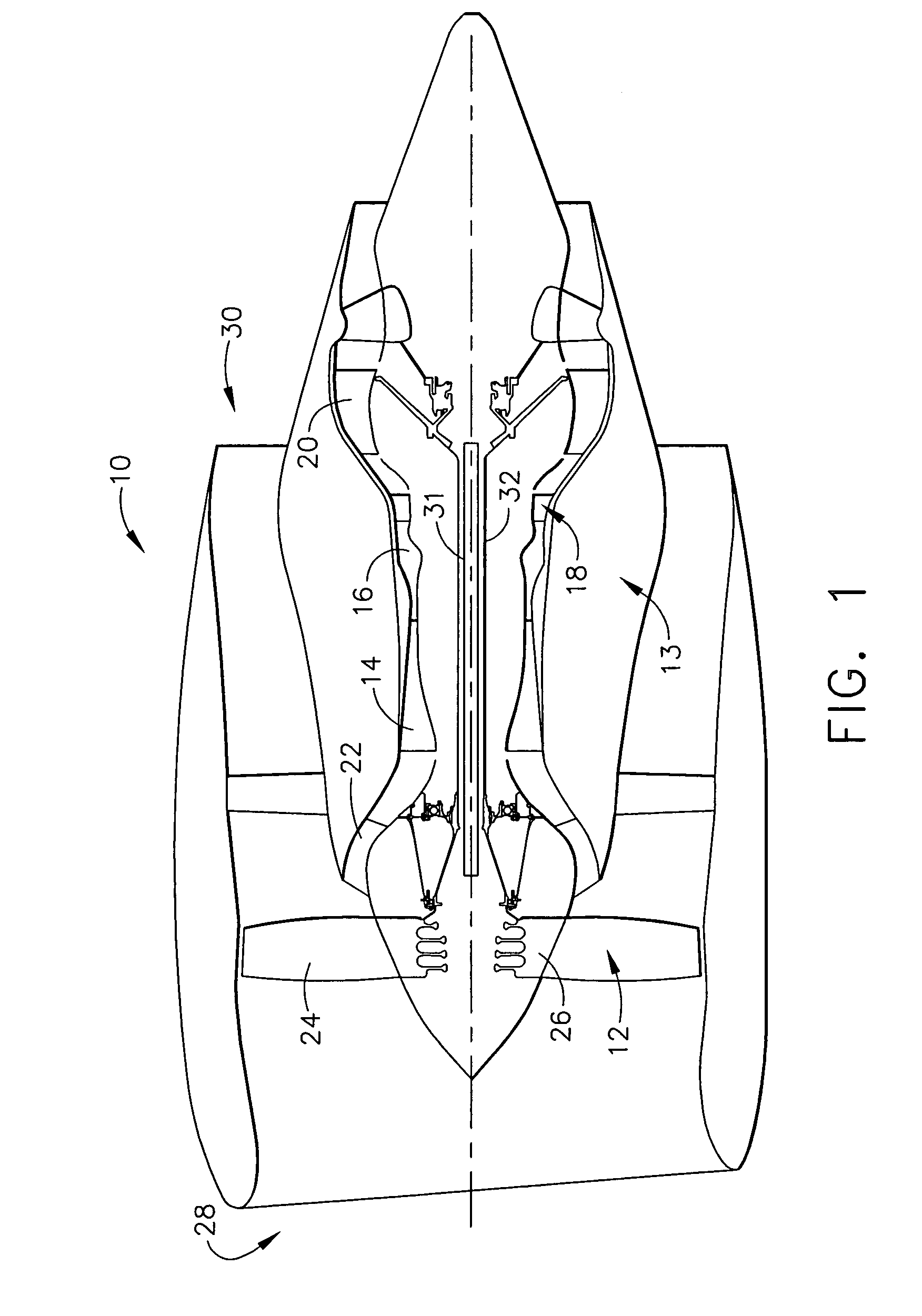
[0013]FIG. 1 is a schematic illustration of a gas turbine engine 10 including a fan assembly 12 and a core engine 13 including a high pressure compressor 14, and a combustor 16. Engine 10 also includes a high pressure turbine 18, a low pressure turbine 20, and a booster 22. Fan assembly 12 includes an array of fan blades 24 extending radially outward from a rotor disc 26. Engine 10 has an intake side 28 and an exhaust side 30. In one embodiment, the gas turbine engine is a GE90 available from General Electric Company, Cincinnati, Ohio. Fan assembly 12 and turbine 20 are coupled by a first rotor shaft 31, and compressor 14 and turbine 18 are coupled by a second rotor shaft 32.

[0014]During operation, air flows axially through fan assembly 12, in a direction that is substantially parallel to a central axis 34 extending through engine 10, and compressed air is supplied to high pressure compressor 14. The highly compressed air is delivered to combustor 16. Airflow (not shown in FIG. 1) f...


PUM

PropertyMeasurementUnit
shapeaaaaaaaaaa
critical bore shapeaaaaaaaaaa
lengthaaaaaaaaaa

Abstract

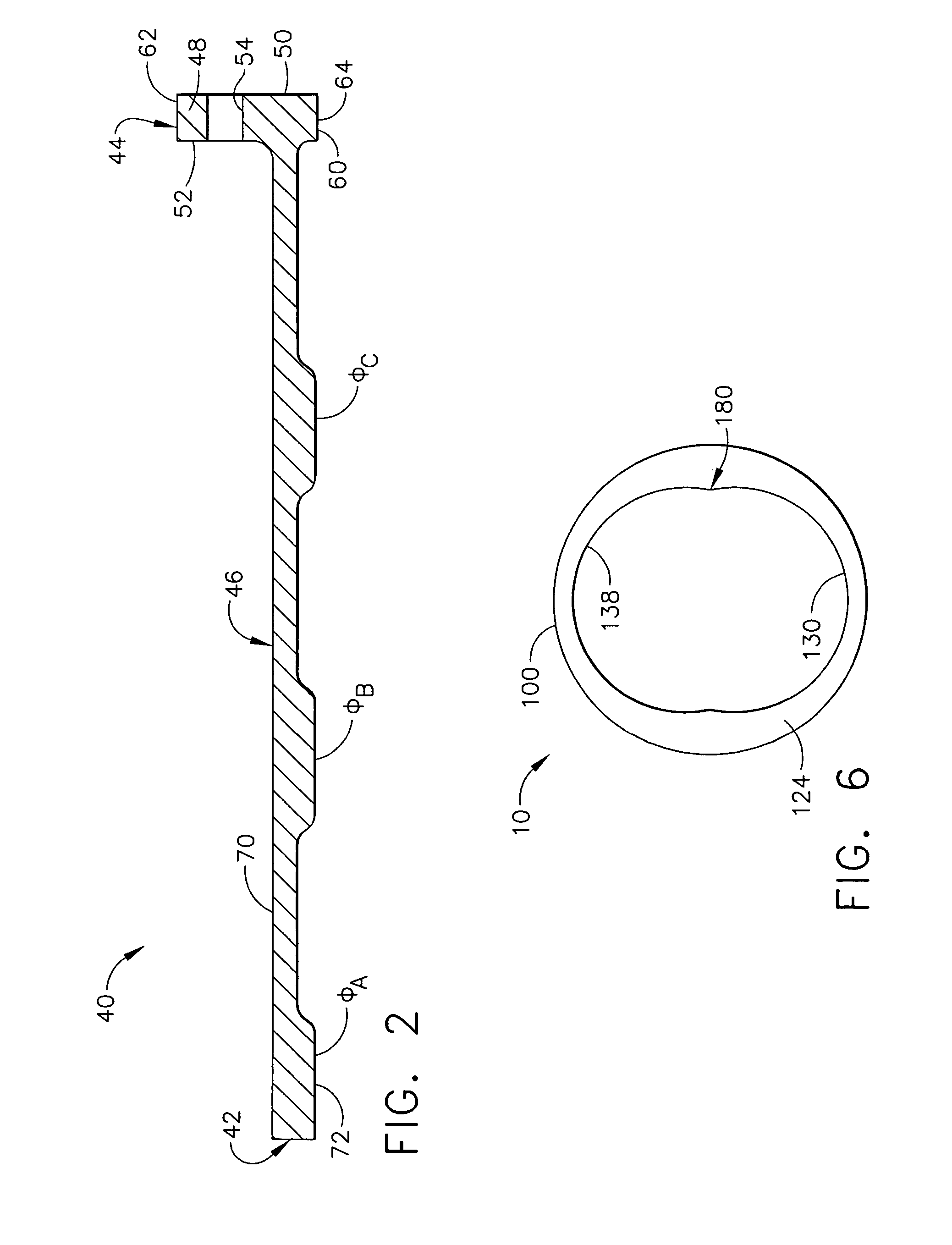
A method facilitates the assembly of a stator assembly for a turbine engine. The method includes providing a cantilevered shell including a first end and a second end, and coupling a second member within the turbine engine. The method also includes coupling the shell to a frame such that the shell extends circumferentially around at least a portion of the second member such that a non-uniform circumferential radial gap is defined radially between the second member and the shell using methods other than directing machining of an inner surface of the shell, and wherein the non-uniform circumferential radial clearance gap becomes substantially uniform during operation of the engine.

Description

BACKGROUND OF THE INVENTION[0001]This application relates generally to turbine engines, and more particularly, to structural shells used in axial flow gas turbine engine systems.[0002]Axial flow gas turbine engines typically includes a plurality of second members, such as a fan rotor assembly, a booster assembly, a compressor, and a turbine. The fan rotor assembly includes a fan including an array of fan blades extending radially outward from a rotor shaft. The rotor shaft transfers power and rotary motion from the turbine to the compressor and the fan, and is supported longitudinally with a plurality of bearing assemblies. Bearing assemblies support the rotor shaft and typically include rolling elements located within an inner race and an outer race.[0003]Structural casings extend around the turbomachinery such that radial clearances are defined therebetween. Inadequate clearances defined within the turbine engincs, such as, but not limited to clearances between rotating seals and ...

Claims


Application Information

Patent Timeline
Patent Type & Authority Patents(United States)
IPC IPC(8): B21K25/00B21K3/04F01D25/00F01D25/16F01D25/24F02C7/06
CPCF01D25/16F01D25/164F05D2230/60Y10T29/4984Y10T29/49321Y10T29/49323Y10T29/4932Y10T29/49318
Inventor SCHILLING, JAN CHRISTOPHERMOLLMANN, DANIEL EDWARDALLMON, BARRY LYNNDURCHHOLZ, ANTHONY
Owner GENERAL ELECTRIC CO
Why Eureka
Try Eureka