
Internal combustion engine hydraulic fuel pump

a fuel pump and hydraulic technology, applied in the direction of fuel injecting pump, fuel injection apparatus, electrical control, etc., can solve the problems of overheating fuel, high energy efficiency of the above type of injection system, and prone to heat, so as to achieve the effect of cheap and easy production

Inactive Publication Date: 2007-08-28
FAB ITAL MAGNETI MARELLI SPA
View PDF10 Cites 1 Cited by
  • Summary
  • Abstract
  • Description
  • Claims
  • Application Information

AI Technical Summary

Benefits of technology

[0011]Moreover, the fact that the high-pressure pump pistons perform one cycle (i.e. one intake stroke and one pump stroke) for each rotation, as opposed to every two rotations, of the drive shaft, means doubling average piston speed, thus resulting in obvious problems in terms of mechanical strength and long-term reliability. Alternatively, it has been proposed to use high-pressure pumps comprising four cylinders and, hence, four pistons, each of which performs one cycle for every two rotations of the drive shaft. Though simpler to produce, this solution greatly increases the cost and size of the high-pressure pump.
[0013]It is an object of the present invention to provide an internal combustion engine fuel pump designed to eliminate the aforementioned drawbacks, and which, in particular, is cheap and easy to produce.

Problems solved by technology

Known injection systems of the above type have various drawbacks, on account of the high-pressure pump necessarily being designed to supply the common rail with slightly more fuel than can possibly be consumed in the maximum consumption condition.
Since the maximum consumption condition, however, occurs fairly rarely, this means that in all other operating conditions, the high-pressure pump supplies the common rail with much more fuel than is actually consumed, and large part of the fuel must be drained by the pressure regulator into the recirculating channel.
Since the work performed by the high-pressure pump, to pump fuel which is ultimately drained by the pressure regulator, is clearly “superfluous”, the energy efficiency of injection systems of the above type is extremely low.
Moreover, known injection systems of the above type tend to overheat the fuel.
That is, when drained by the pressure regulator into the recirculating channel, the surplus fuel passes from a very high pressure to substantially atmospheric pressure, and as a result tends to heat.
Finally, known injection systems of the above type are fairly bulky, on account of the pressure regulator and the recirculating channel connected to it.
The resulting disparity between the two injectors injecting fuel during the same rotation of the drive shaft produces, for a given injection time, a difference in the amount of fuel injected by the two injectors, which obviously affects correct performance of the engine.
This obviously reduces the disparity in performance of the injectors, in that, within the same control interval, the injectors either all inject fuel while one of the high-pressure pump pistons is pumping fuel into the common rail, or all inject fuel while neither of the high-pressure pump pistons is pumping fuel into the common rail.
Moreover, the fact that the high-pressure pump pistons perform one cycle (i.e. one intake stroke and one pump stroke) for each rotation, as opposed to every two rotations, of the drive shaft, means doubling average piston speed, thus resulting in obvious problems in terms of mechanical strength and long-term reliability.
Though simpler to produce, this solution greatly increases the cost and size of the high-pressure pump.
In addition, known fuel pumps of the type described above are complicated and expensive to produce, by having to control the control member delaying the instant the intake valve closes; and fuel flows continuously through the intake valve to and from the cylinder, thus obviously wasting part of the energy used by the pump.
Finally, such fuel pumps must be connected mechanically to the drive shaft for the drive shaft to produce the reciprocating movement necessary to drive the piston, thus imposing severe restrictions in terms of location of the fuel pump inside the engine compartment. cl SUMMARY OF THE INVENTIO

Method used


Image

  • Internal combustion engine hydraulic fuel pump
  • Internal combustion engine hydraulic fuel pump
  • Internal combustion engine hydraulic fuel pump

Examples


Embodiment Construction

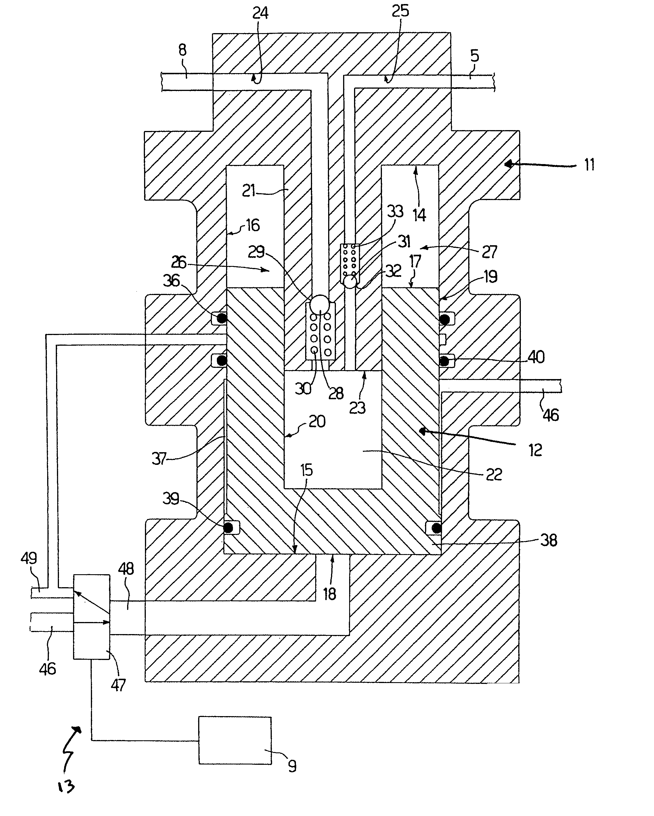
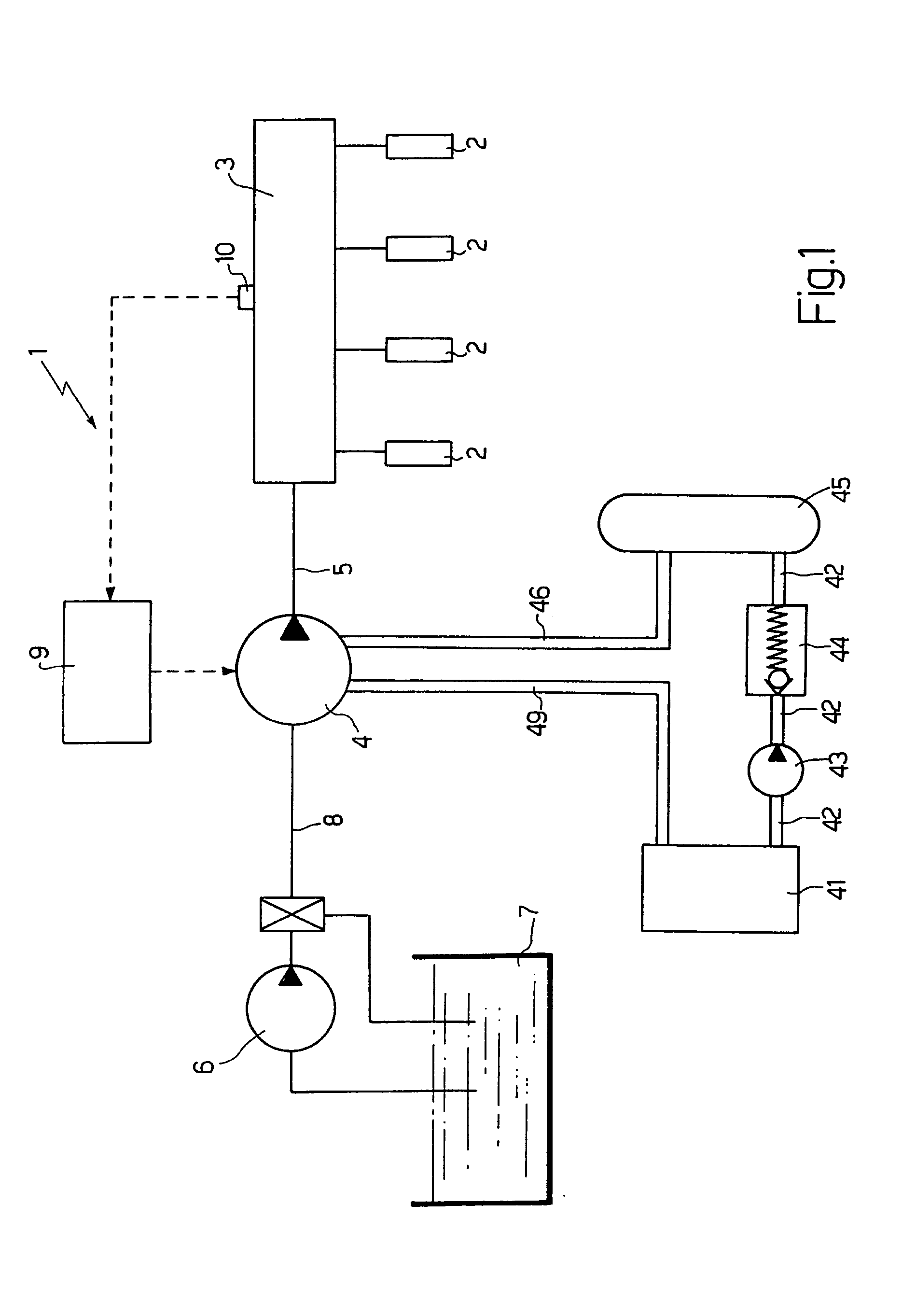
[0018]Number 1 in FIG. 1 indicates as a whole a common-rail system for direct fuel injection into an internal combustion engine having four cylinders (not shown in detail). Injection system 1 comprises four injectors 2, each of which injects fuel directly into the top of a respective cylinder (not shown in detail) of the engine, and is supplied with pressurized fuel by a common rail 3. A high-pressure pump 4 feeds fuel to common rail 3 along a pipe 5, and is supplied with fuel by a low-pressure pump 6, which draws fuel from a tank 7 and is connected to high-pressure pump 4 by a pipe 8.

[0019]A control unit 9 regulates the delivery of high-pressure pump 4 to keep the fuel pressure in common rail 3 equal to a desired value, which normally varies as a function of engine operating conditions. Control unit 9 preferably regulates the delivery of high-pressure pump 4 by feedback control, using, as a feedback variable, the real-time fuel pressure value in common rail 3 detected by a sensor 1...


PUM


Abstract

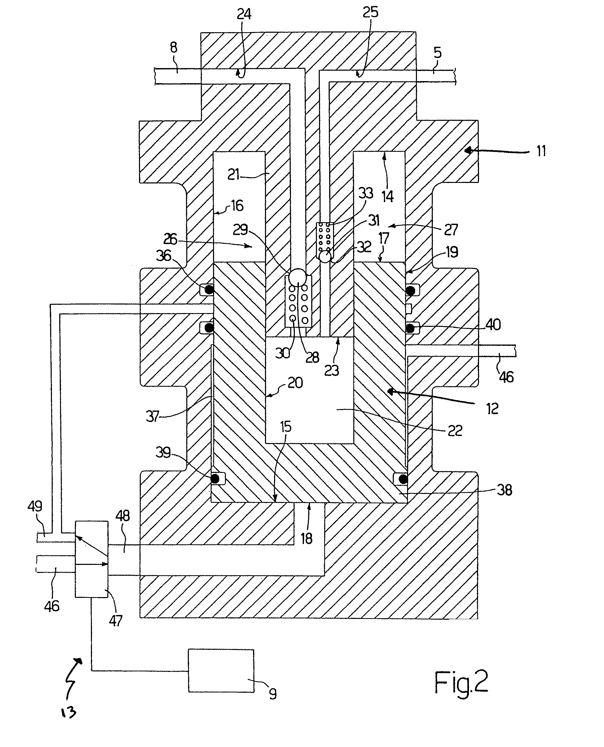
An internal combustion engine fuel pump having at least one cylinder, in which a variable-volume pump chamber is defined; a movable piston defining the bottom of the pump chamber; at least one intake valve communicating with the pump chamber; at least one delivery valve communicating with the pump chamber; and a hydraulic / pneumatic actuating device for moving the piston back and forth with respect to the cylinder to cyclically vary the volume of the pump chamber; the hydraulic / pneumatic actuating device has a first actuating chamber located beneath the pump chamber, a second actuating chamber located above the first actuating chamber, and a control member for cyclically filling the first actuating chamber with pressurized oil.

Description

[0001]The present invention relates to an internal combustion engine fuel pump.[0002]The fuel pump according to the present invention may be used to advantage as a high-pressure fuel pump in a common-rail direct fuel injection system, to which the following description refers purely by way of example. cl BACKGROUND OF THE INVENTION[0003]In currently used common-rail direct fuel injection systems, a low-pressure pump feeds fuel from a tank to a high-pressure pump, which in turn feeds the fuel to a common rail; and a number of injectors are connected to the common rail and controlled cyclically to inject part of the pressurized fuel in the common rail into respective cylinders. The high-pressure pump comprises at least one cylinder with a piston controlled mechanically by the drive shaft to slide back and forth inside the cylinder; a one-way intake valve permitting fuel flow into the cylinder along an intake channel; and a one-way delivery valve connected to a delivery channel termina...

Claims


Application Information

Patent Timeline
Patent Type & Authority Patents(United States)
IPC IPC(8): F02M57/02
CPCF02M59/105F02M59/107F02M59/30F02M63/0225F02M63/023F02M63/0265F02D41/3845F02D41/406
Inventor CIAMPOLINI, FRANCO
Owner FAB ITAL MAGNETI MARELLI SPA
Learn More