Equipment for fine positioning of a car of a multi-stage car

a technology of car and car body, applied in the direction of elevators, machine supports, building scaffolds, etc., to achieve the effect of simple construction

Active Publication Date: 2007-08-28
INVENTIO AG
View PDF22 Cites 6 Cited by
  • Summary
  • Abstract
  • Description
  • Claims
  • Application Information

AI Technical Summary

Benefits of technology

[0004]The present invention avoids the disadvantages of the known equipment and creates adjusting equipment which is of simple construction.
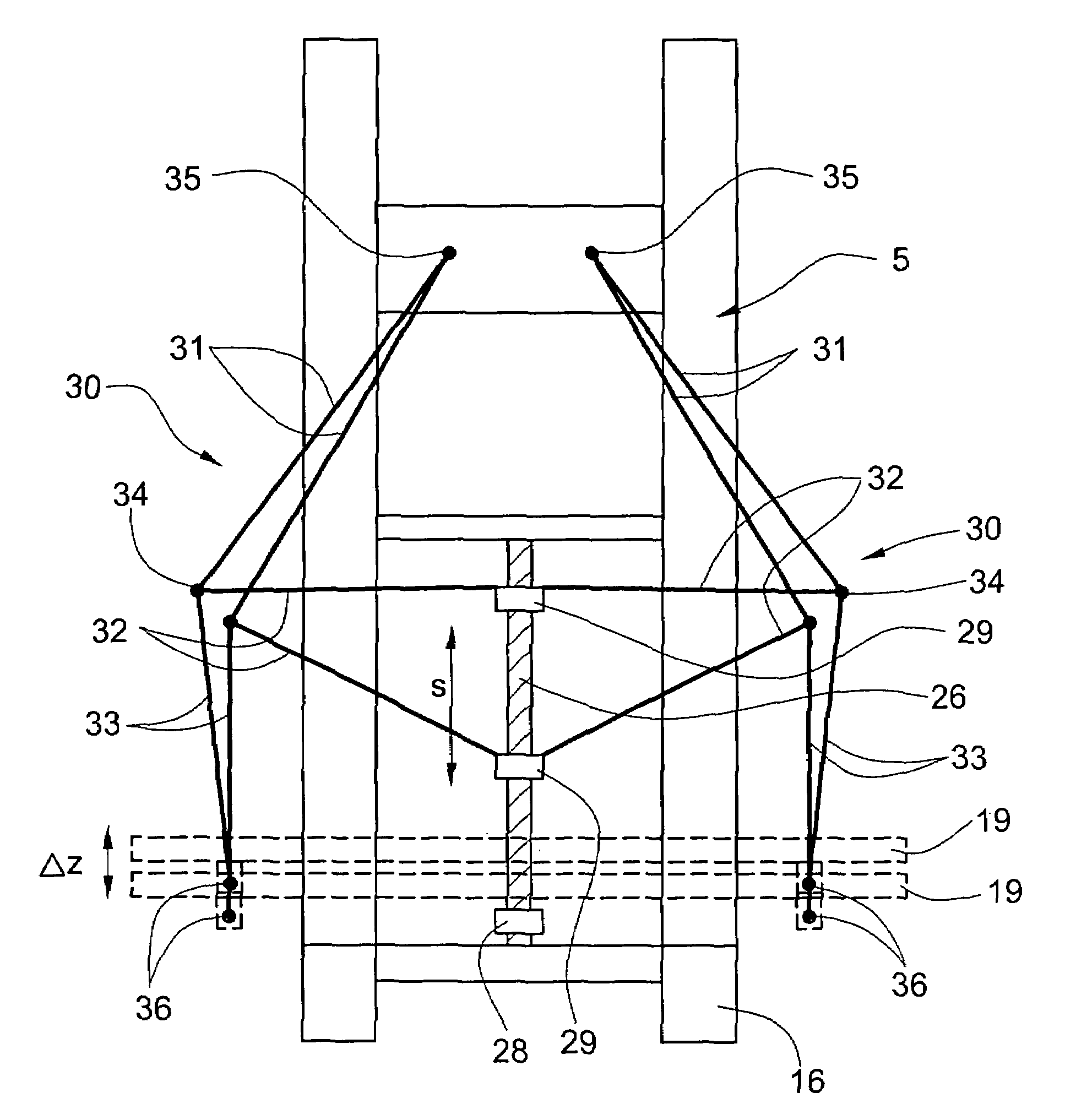
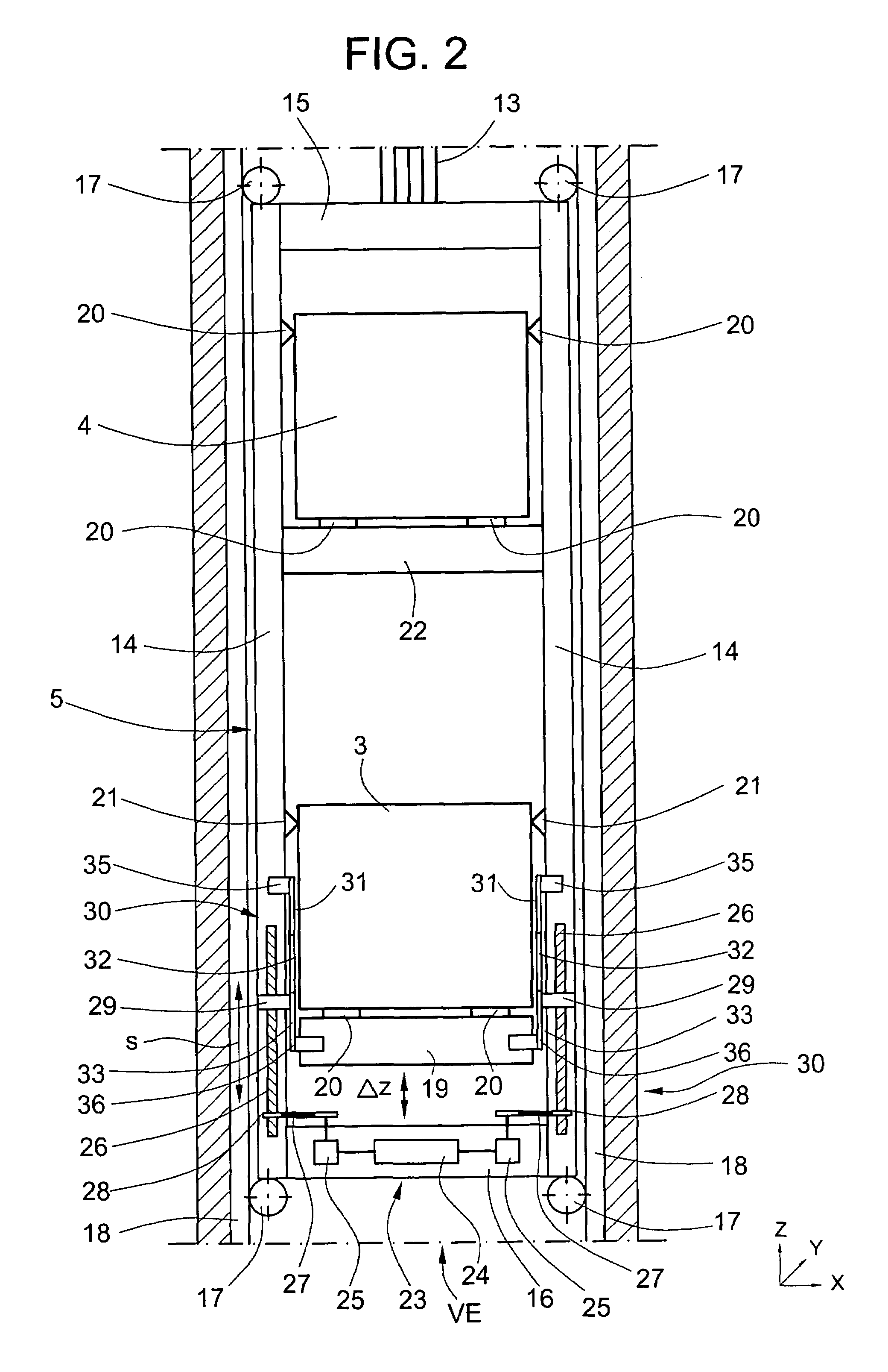
[0005]The advantages achieved by the present invention are that with this adjusting equipment a doubled lever translation can be executed, which in turn enables a smaller adjusting drive. Of further advantage is the fact that the adjusting equipment according to the present invention has a more linear force path. The adjusting mechanism can be mounted laterally of the car, whereby the intermediate yoke is loaded only by one car. The forces are introduced directly into side panels. The drive arranged below the car has a lesser space requirement. No adjusting equipment is necessary for the further car and thus also no car guide is required.

Problems solved by technology

A disadvantage of this known equipment resides in the fact that the pantograph engaging the intermediate yoke loads the intermediate yoke with two cars.

Method used


Image

  • Equipment for fine positioning of a car of a multi-stage car
  • Equipment for fine positioning of a car of a multi-stage car
  • Equipment for fine positioning of a car of a multi-stage car

Examples


Embodiment Construction

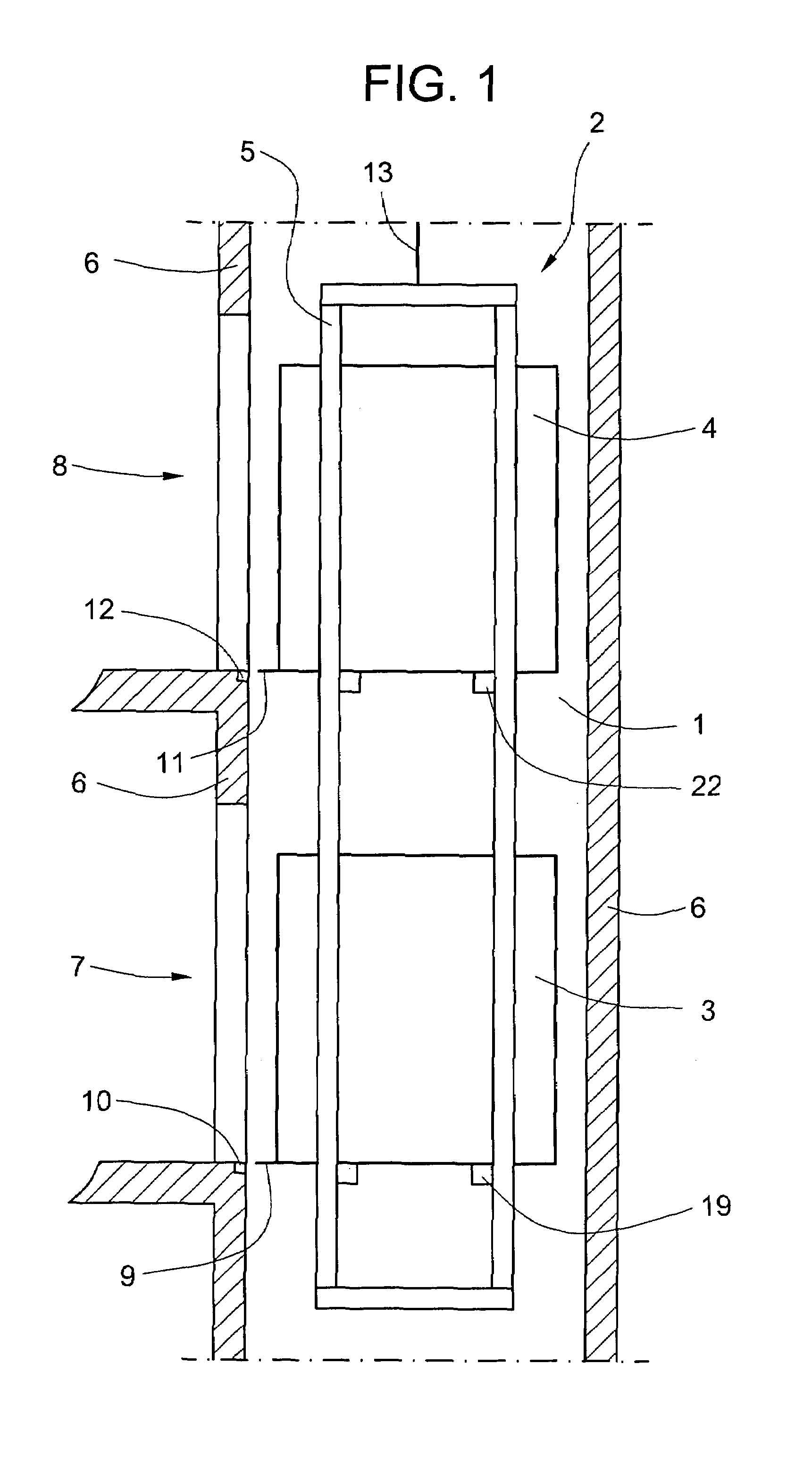
[0013]FIG. 1 shows a multi-stage car 2 which is movable in an elevator shaft 1 and which consists of a lower car 3 and an upper car 4, which cars are arranged in a main frame 5. The elevator shaft 1 is formed from shaft walls 6, wherein an opening which serves for access to the multi-stage car 2 and which is closed by a floor door (not illustrated) is provided for each floor. The openings of the elevator cars 3, 4 are closed by car doors (not illustrated). An uneven-numbered floor is denoted by 7 and an even-numbered floor by 8. The lower car 3 stands at the uneven-numbered floor 7 and the upper car 4 stands at the even-numbered floor 8. After positioning of the lower car 3 a car threshold 9 is flush in terms of level with a floor threshold 10. After positioning of the upper car 4 a car threshold 11 is flush in terms of level with a floor threshold 12. The drive for the multi-stage car 2 is not illustrated, wherein supporting and driving means, for example cables 13, are guided over...


PUM


Abstract

A multi-stage elevator car has equipment for fine positioning of the cars wherein the car thresholds are positionable at the level of the floor thresholds. The fine positioning adjusting equipment operates on the principle of a double lever and moves a car frame along a path (Δz).

Description

BACKGROUND OF THE INVENTION[0001]The present invention relates to equipment for fine positioning a car of a multi-stage car for an elevator, wherein the thresholds of the cars are positionable at the level of the floor thresholds.[0002]An elevator with a multi-stage car is shown in the European patent specification EP 0 870 716, consisting of a main frame in which two cars are arranged. A pantograph operating on the scissors principle centrally engages at an intermediate yoke. One end of the pantograph is pivotably connected with the lower yoke of the upper car and the other end of the pantograph is pivotably connected with the upper yoke of the lower car. Two spindle drives are provided at the upper yoke of the main frame and move the upper car up and down. In the case of upward movement of the upper car, the pantograph extends, whereby the lower car executes a downward movement. In the case of downward movement of the upper car, the pantograph contracts, whereby the lower car exec...

Claims


Application Information

Patent Timeline
Patent Type & Authority Patents(United States)
IPC IPC(8): B66B9/00B66B1/24B66B1/36B66B1/40B66B1/42
CPCB66B1/40B66B11/0095B66B11/022
Inventor STREBEL, RENEHOFFMANN, RENESCHAFFHAUSER, URS
Owner INVENTIO AG
Why Eureka
Try Eureka