
Collision time estimation apparatus for vehicles, collision time estimation method for vehicles, collision alarm apparatus for vehicles, and collision alarm method for vehicles

a technology for collision alarms and vehicles, which is applied in traffic control systems, transportation and packaging, instruments, etc., can solve the problems of inability to easily calculate collision time, increase computation complexity, and increase the amount of movement of edges, so as to facilitate the calculation of collision time, reduce the effect of collision alarms and robust output against position detection errors

Active Publication Date: 2007-08-28
NISSAN MOTOR CO LTD
View PDF5 Cites 19 Cited by
  • Summary
  • Abstract
  • Description
  • Claims
  • Application Information

AI Technical Summary

Benefits of technology

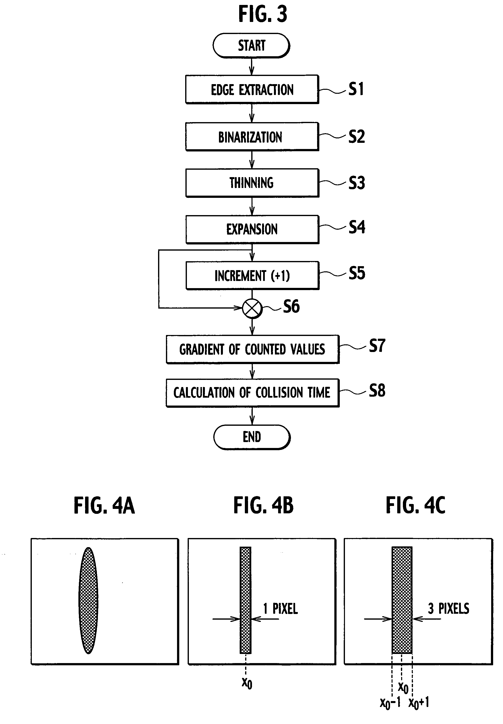
The present invention provides a collision time estimation apparatus and a collision time estimation method for vehicles that can accurately calculate the time of collision with an object that has the possibility of collision with a subject vehicle. This is achieved by standardizing the edge width of an edge image, incrementing a count value corresponding to a position where the standardized edge image is detected, and calculating the movement amount and speed of the edge image based on the inclination of the count values. The invention also extracts a longitudinal edge image and a lateral edge image from the picked up image, calculates the movement amount of the images, and extracts an image area containing an object having a possibility of collision as a noticeable area. The technical effects of the invention are facilitation of calculation of collision time and robust output against errors in position detection.

Problems solved by technology

When an optical flow is detected by using the correlation method, however, the computational complexity increases because a region to calculate a correlation value is provided around a noticeable area and a brightness correlation value within the region between two frames of different times is detected, and therefore the collision time cannot be calculated easily.
This means that, when an error occurs in detection of edge position, the movement amount of the edge may contain this error.
Therefore, according to the conventional collision alarm apparatus for vehicles, when an object which leads the subject vehicle to dangerous situations, such as an object suddenly coming in right ahead, cutting in, or merging, moves in a lateral direction of the subject vehicle, it is not possible to determine whether the collision time is calculated for an object having the possibility of collision with the subject vehicle, and thus the collision time cannot be calculated properly.

Method used


Image

  • Collision time estimation apparatus for vehicles, collision time estimation method for vehicles, collision alarm apparatus for vehicles, and collision alarm method for vehicles
  • Collision time estimation apparatus for vehicles, collision time estimation method for vehicles, collision alarm apparatus for vehicles, and collision alarm method for vehicles
  • Collision time estimation apparatus for vehicles, collision time estimation method for vehicles, collision alarm apparatus for vehicles, and collision alarm method for vehicles

Examples


Embodiment Construction

[0026]With reference to the accompanying drawings, configurations of a collision time estimation apparatus for vehicles and a collision alarm apparatus for vehicles according to the preferred embodiments of the present invention will be described below.

Configuration of Collision Time Estimation Apparatus for Vehicles

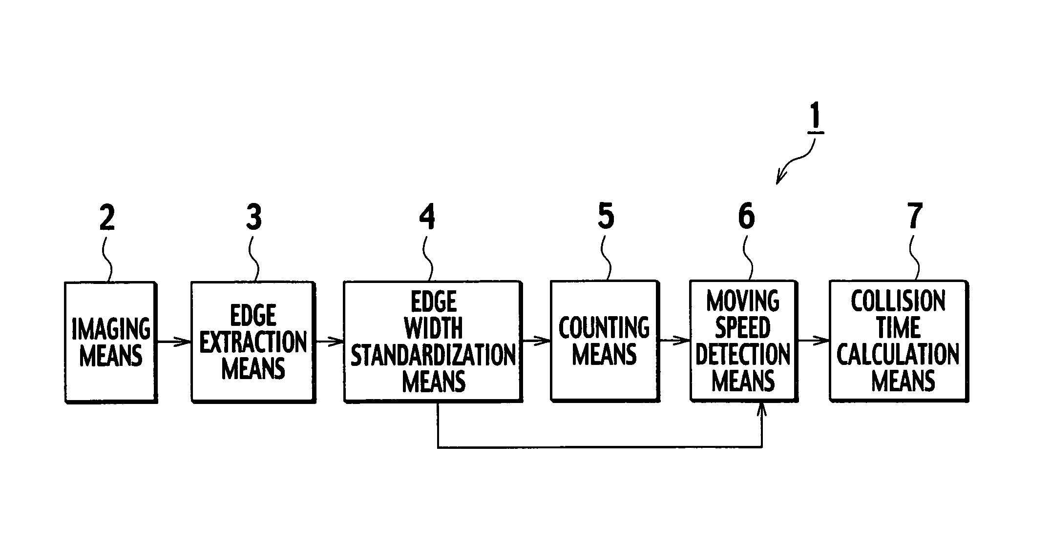
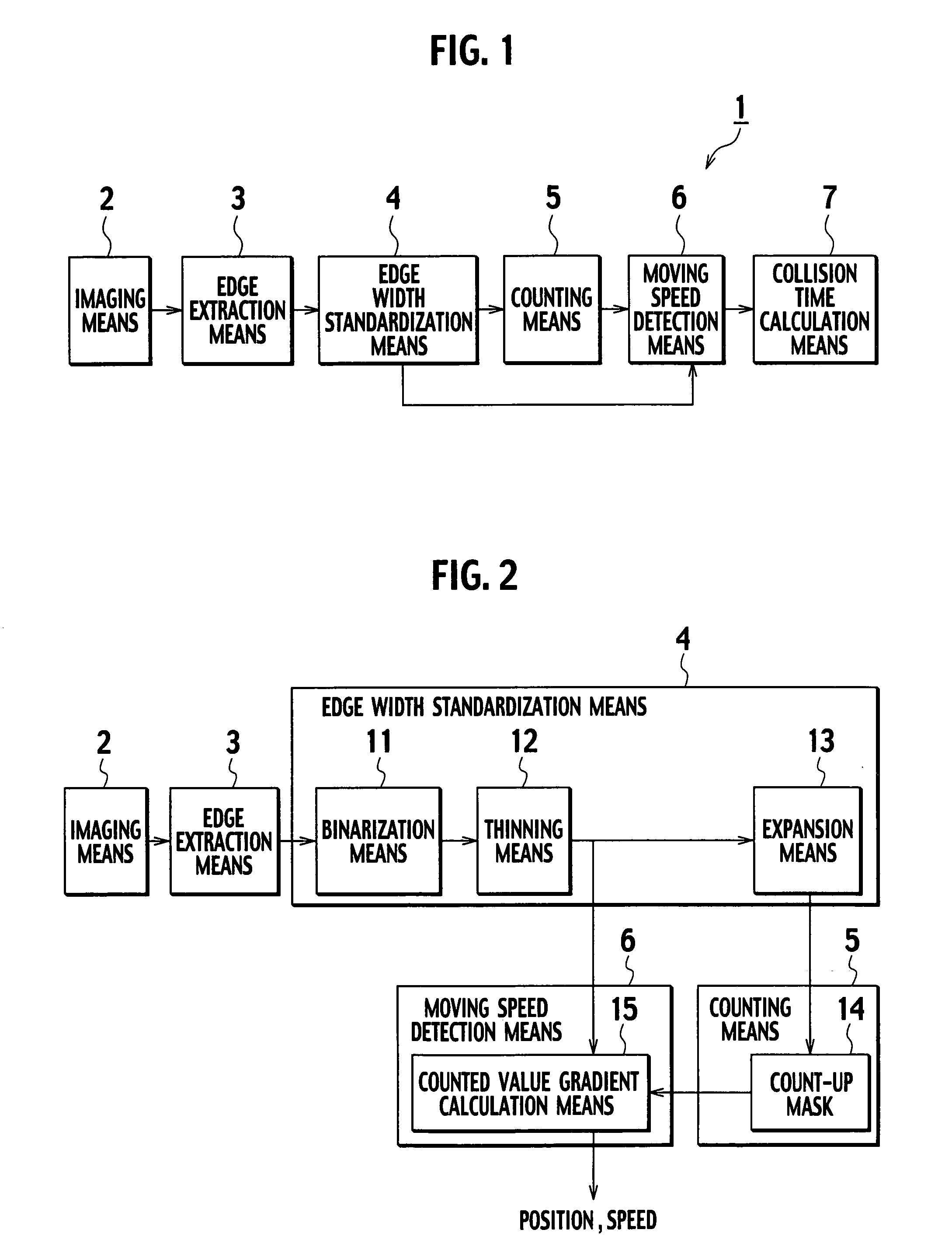
[0027]A collision time estimation apparatus for vehicles 1 according to an embodiment of the present invention is provided in a vehicle and includes, as shown in FIG. 1, imaging means 2 for picking up an image of the area around a vehicle, edge extraction means 3 for extracting an edge image, by using a Sobel filter, from temporally successive images picked up by the imaging means 2, edge width standardization means 4 for standardizing the edge width of the edge image extracted by the edge extraction means 3 to a predetermined number of pixels, counting means 5 for storing, as a count-up mask 14 (see FIG. 2), information as to over how many frames the standardized edge i...


PUM


Abstract

Imaging device picks up an image of the area around a vehicle, edge extraction function extracts an edge image from the image picked up by the imaging device, edge width standardization function standardizes an edge width of the edge image extracted by the edge extraction function, counting functions increments a count value corresponding to a position where the edge image standardized by the edge width standardization function is detected, and also initializes a count value corresponding to a position where the standardized edge image is not detected, moving speed detection function calculates a moving direction and moving speed of the edge image extracted by the edge extraction function based on the inclination of the count values, and collision time calculation function calculates the time of collision with an object by utilizing the position and the moving speed of the edge image calculated by the moving speed detection function.

Description

BACKGROUND OF THE INVENTION[0001]The present invention relates to a collision time estimation apparatus for vehicles that is provided in a vehicle and estimates the time of collision with an object, and also to a collision time estimation method for vehicles. The present invention further relates to a collision alarm apparatus and a collision alarm method for vehicles that estimate the time of collision with an object having the possibility of collision with a subject vehicle, and based on the estimation result, raise an alarm of the possible collision for a driver or control the vehicle in order to avoid the collision with the object.[0002]As disclosed in Japanese Patent Application Laid-Open No. H11-353565, conventionally, there is a collision time estimation apparatus for vehicles that detects horizontal or vertical edges of an object having the possibility of collision, from two images of surrounding areas of a vehicle which are picked up at different times, then calculates an o...

Claims


Application Information

Patent Timeline
Patent Type & Authority Patents(United States)
IPC IPC(8): G08G1/16
CPCG08G1/163
Inventor WATANABE, SEIGOOSHIMA, RUMIKOSAKAMOTO, MASAHIKO
Owner NISSAN MOTOR CO LTD
Learn More