Vehicular vision system

a technology of vision system and eye, applied in the field of eye vision system, can solve the problems of not providing any information regarding the movement of the obstacle, not classifying the obstacle, etc., and achieve the effect of avoiding the obstacle and reducing the damage resulting

Active Publication Date: 2007-08-28
FORD MOTOR CO
View PDF14 Cites 77 Cited by
  • Summary
  • Abstract
  • Description
  • Claims
  • Application Information

AI Technical Summary

Benefits of technology

[0007]The invention provides a vision system for a vehicle that identifies and classifies objects (targets) located proximate a vehicle. The system comprises a sensor array that produces imagery that is processed to generate depth maps (or depth images) of the scene proximate a vehicle. The depth maps are processed and compared to pre-rendered templates of target objects that could appear proximate the vehicle. A target list is produced by matching the pre-rendered templates to the depth map imagery. The system processes the target list to produce target size and classification estimates. The target is then tracked as it moves near a vehicle and the target position, classification and velocity are determined. This information can be used in a number of ways. For example, the target information may be displayed to the driver, or the information may be used for an obstacle avoidance system that adjusts the trajectory or other parameters of the vehicle to safely avoid the obstacle. The orientation and / or configuration of the vehicle may be adapted to mitigate damage resulting from an imminent collision, or the driver may be warned of an impending collision.

Problems solved by technology

These collision avoidance systems identify that an obstacle exists in front of a vehicle, but do not classify the obstacle nor provide any information regarding the movement of the obstacle.

Method used


Image

  • Vehicular vision system
  • Vehicular vision system
  • Vehicular vision system

Examples


Embodiment Construction

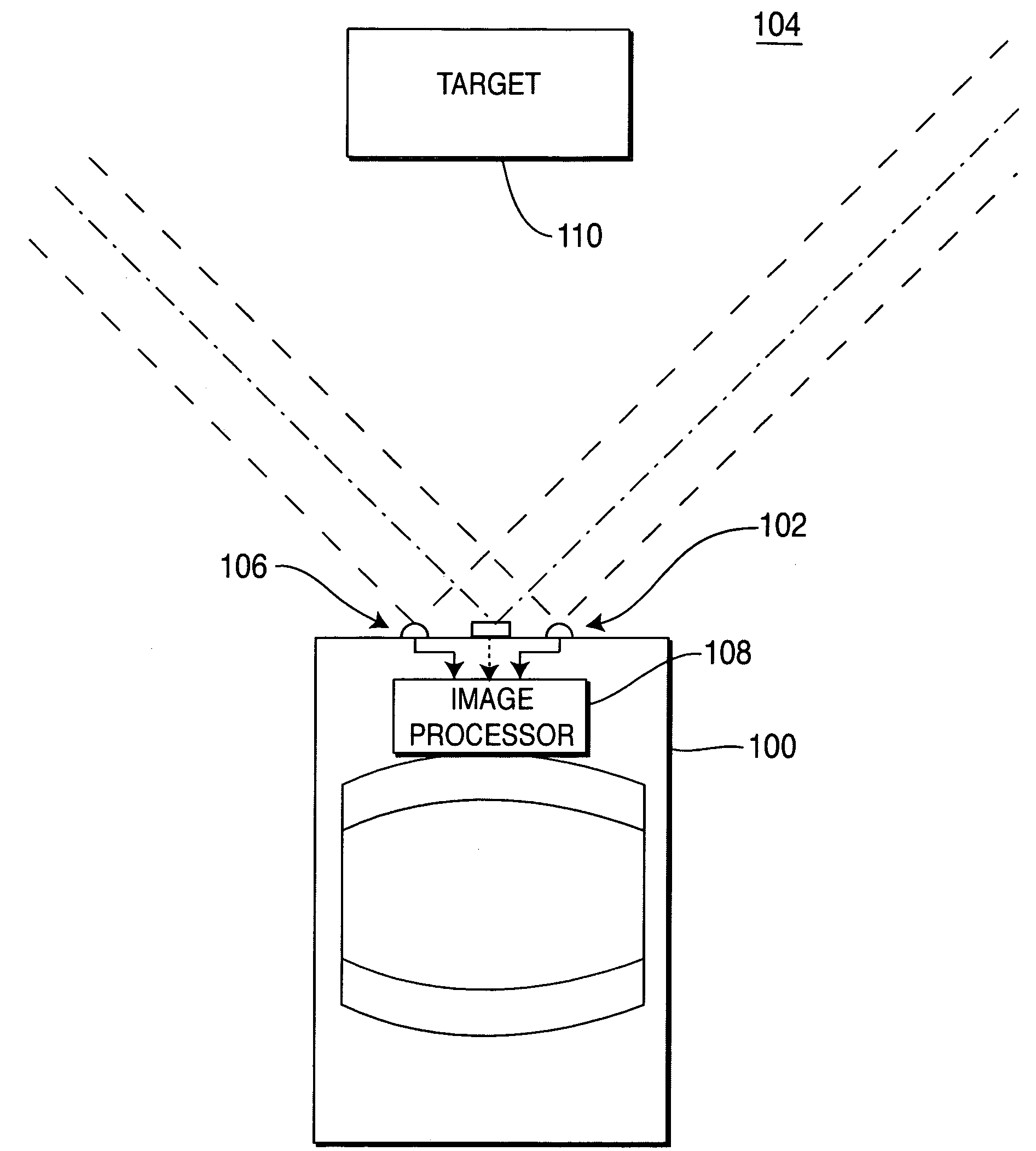
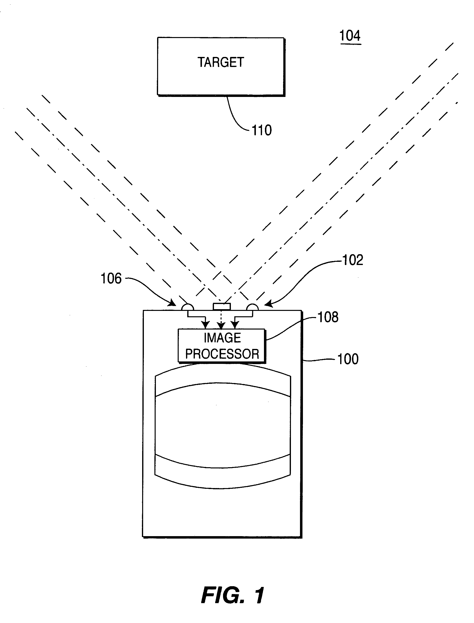
[0014]FIG. 1 depicts a schematic diagram of a vehicle 100 utilizing a vision system 102 to image a scene 104 that is located proximate vehicle 100. In the embodiment shown, the imaged scene is in front of the vehicle 100. Other applications of the system 102 may image a scene that is behind or to the side of the vehicle. The vision system 102 comprises sensor array 106 coupled to an image processor 108. The sensors within the array 106 have a field of view that images a target 110 that is located in front of the vehicle 100. The field of view of the sensors in a practical system may be ±12 meters horizontally in front of the automobile (e.g., approximately 3 traffic lanes), a ±3 meter vertical area and provides a view of approximately 40 meters in front of the vehicle.

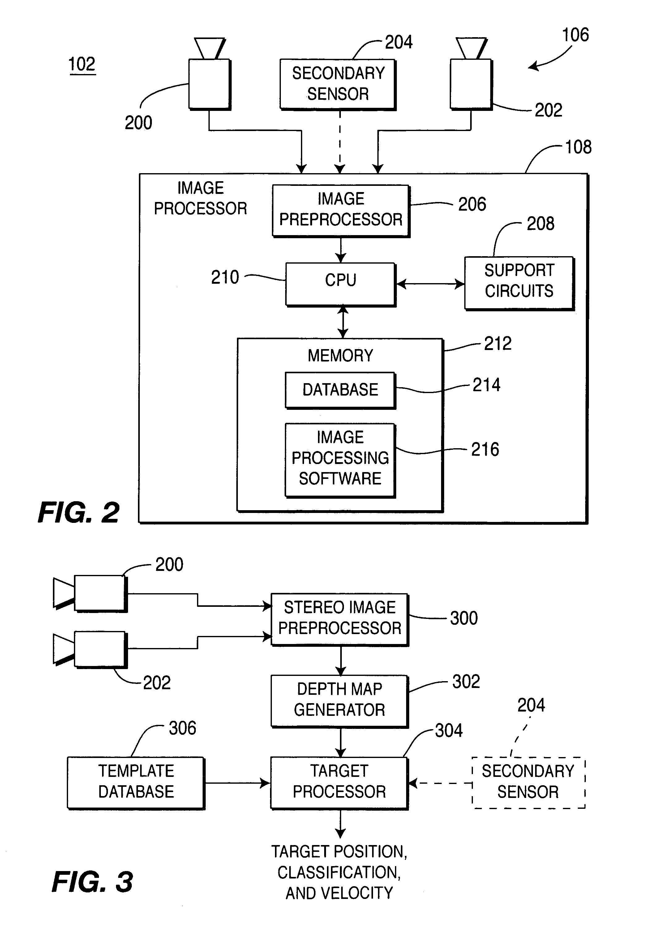
[0015]FIG. 2 depicts a block diagram of the hardware used to implement the vision system 102. The sensor array 106 comprises, for example, a pair of optical cameras 200 and 202 and an optional secondary sensor 204. The...


PUM


Abstract

A vision system for a vehicle that identifies and classifies objects (targets) located proximate a vehicle. The system comprises a sensor array that produces imagery that is processed to generate depth maps of the scene proximate a vehicle. The depth maps are processed and compared to pre-rendered templates of target objects that could appear proximate the vehicle. A target list is produced by matching the pre-rendered templates to the depth map imagery. The system processes the target list to produce target size and classification estimates. The target is then tracked as it moves near a vehicle and the target position, classification and velocity are determined. This information can be used in a number of ways. For example, the target information may be displayed to the driver, the information may be used for an obstacle avoidance system that adjusts the trajectory or other parameters of the vehicle to safely avoid the obstacle. The orientation and/or configuration of the vehicle may be adapted to mitigate damage resulting from an imminent collision, or the driver may be warned of an impending collision.

Description

BACKGROUND OF THE INVENTION[0001]1. Field of the Invention[0002]The present invention relates to vehicular vision systems. In particular, the present invention relates to a method and apparatus for providing target detection to facilitate collision avoidance and / or mitigation.[0003]2. Description of the Related Art[0004]Collision avoidance systems utilize a sensor for detecting objects in front of an automobile or other form of vehicle. The sensor may be a radar, an infrared sensor or an optical vision system. The sensor generates a rudimentary image of the scene in front of the vehicle and, by processing that imagery, obstacles can be detected within the imagery.[0005]These collision avoidance systems identify that an obstacle exists in front of a vehicle, but do not classify the obstacle nor provide any information regarding the movement of the obstacle. As such, the driver of the vehicle may be warned of an obstacle or the automobile may take evasive action regarding an obstacle,...

Claims


Application Information

Patent Timeline
Patent Type & Authority Patents(United States)
IPC IPC(8): G06K9/00B60Q1/00G06K9/32G06T7/00G06T7/20
CPCG06K9/00201G06K9/3241G06K9/00805G06T7/20G06T7/0065G06T2207/20064G06T2207/30252G06T7/593G06V20/64G06V20/58G06V10/255
Inventor CAMUS, THEODORE ARMANDHIRVONEN, DAVIDMANDELBAUM, ROBERTCALL, BILLIE JOEHILL, IAN GREGORYRIEDER, ANDRESOUTHALL, JOHN BENJAMIN
Owner FORD MOTOR CO
Why Eureka
Try Eureka