Unlock instant, AI-driven research and patent intelligence for your innovation.

Method, apparatus and system for the automatic provisioning of a network element

a network element and automatic provisioning technology, applied in the field of optical network systems, can solve the problems of critical network management tasks such as provisioning, the size and complexity of data communication networks such as optical line systems are continually increasing, and the complexity of network management functions is proportional to increas

Inactive Publication Date: 2007-08-28
LUCENT TECH INC
View PDF4 Cites 6 Cited by
  • Summary
  • Abstract
  • Description
  • Claims
  • Application Information

AI Technical Summary

Benefits of technology

"The present invention provides a method for automatically provisioning optical translators that support multiple frequencies. This allows for the efficient and effective connection of optical lines, reducing the time and effort required for installation. The method can be used in both end terminals and optical add / drop multiplexers, making it easy to automatically provision optical circuits in an optical line system. Overall, the invention improves the efficiency and reliability of optical line connections."

Problems solved by technology

Data communication networks such as optical line systems are continually increasing in both size and complexity.
As these networks and systems increase in size, the network management functions proportionally increase in complexity.
This means that the critical tasks of network management, such as provisioning (allocating resources to form a communications link), restoration, reinstatement, and such are also further complicated as networks and systems grow.
It is becoming increasingly difficult to efficiently provision optical line systems (OLSs), since the number of fibered connections in a typical OLS may take days to manually provision.
However, manual entry of the commands was very time consuming and prone to error, since the process could easily take several hours and require several hundred commands to be entered for the addition of a single network element.

Method used


Image

  • Method, apparatus and system for the automatic provisioning of a network element
  • Method, apparatus and system for the automatic provisioning of a network element
  • Method, apparatus and system for the automatic provisioning of a network element

Examples


Embodiment Construction

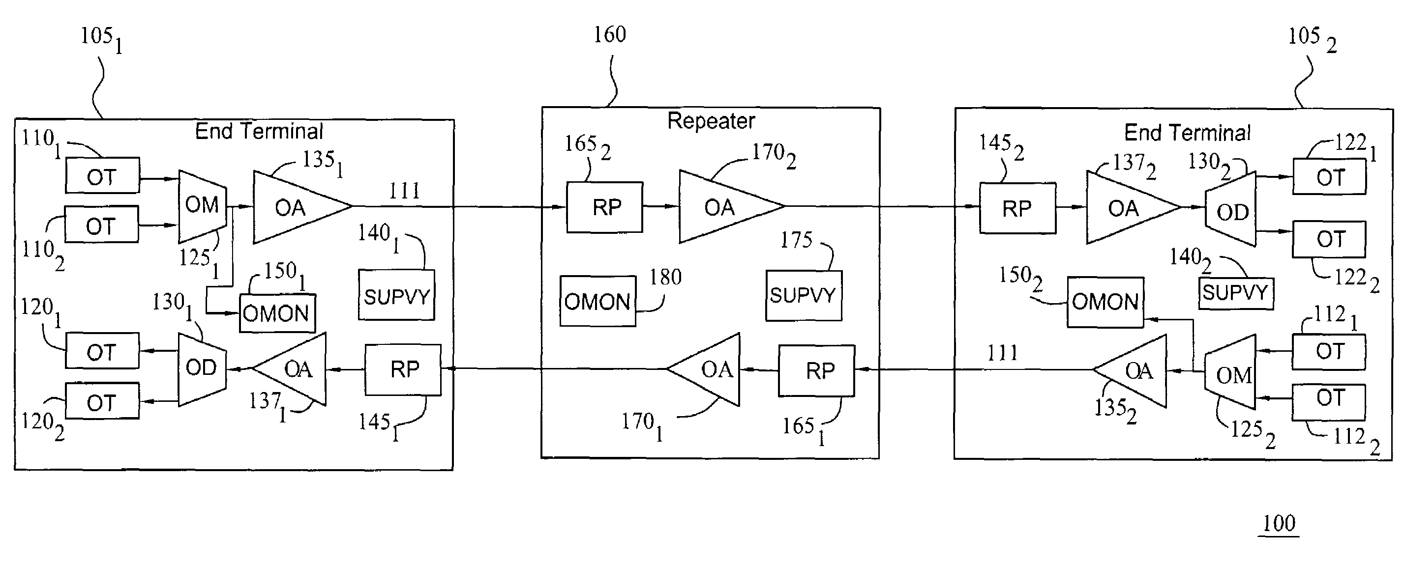
[0014]The present invention provides a novel method, apparatus and system for the automatic provisioning of a network element. Although various embodiments of the present invention herein are being described with respect to the automatic provisioning of end terminals comprising tunable optical translators, it will be appreciated by those skilled in the relevant art informed by the teachings of the present invention, that the concepts of the present invention may be used to automatically provision various other network elements, such as optical add / drop modules. Furthermore, although various embodiment of the present invention herein are being described via the implementation of a software transmission code utilizing specific commands, it will be appreciated by those skilled in the relevant art informed by the teachings of the present invention, that other software and hardware comprising substantially similar functionality as the software described herein, may be implemented within ...


PUM


Abstract

A method for the automatic provisioning of a network element (NE) includes receiving a client signal at a tunable optical translator (OT) in the NE, determining the set of channels supported by the OT that are able to correspond to the client signal, eliminating the channels that have connections, that may be present on a line side of the NE in a laser off scan process, or that have not been equipped or otherwise provisioned for transmission, tuning the OT to each of the remaining channels and determining the optical power level of each channel on a line side of the NE in a laser on scan process. Subsequently, the channel with the highest power level is selected to transmit the client signal and associations for a point to point connection for that channel are added for that OT to a database of associations for the NE.

Description

CROSS-REFERENCE TO RELATED APPLICATIONS[0001]This application is related to U.S. patent application Ser. No. 10 / 093,847, filed Mar. 08, 2002, which is incorporated herein by reference in its entirety.FIELD OF THE INVENTION[0002]The present invention relates to the field of optical network systems and, more specifically, to the automatic provisioning of network elements.BACKGROUND OF THE INVENTION[0003]Data communication networks such as optical line systems are continually increasing in both size and complexity. As these networks and systems increase in size, the network management functions proportionally increase in complexity. This means that the critical tasks of network management, such as provisioning (allocating resources to form a communications link), restoration, reinstatement, and such are also further complicated as networks and systems grow.[0004]It is becoming increasingly difficult to efficiently provision optical line systems (OLSs), since the number of fibered conne...

Claims


Application Information

Patent Timeline
Patent Type & Authority Patents(United States)
IPC IPC(8): H04B10/08H04B10/02
CPCH04B10/079
Inventor ADLEMAN, RICHARDBARTMAN, PETER L.BLACH, HERIBERT JOSEPHENG, ELLENRAGHAVAN, NARASIMHANSHI, YANSOCRATOUS, MARYTHOMPSON, WILLIAM A.
Owner LUCENT TECH INC