Single probe downhole sampling apparatus and method

a single probe and sampling apparatus technology, applied in the field of single probe formation testers, can solve the problem of substantially uncontaminated fluid flowing through the sampling tube, and achieve the effect of quick uncontaminated fluid samples

Inactive Publication Date: 2007-09-04
SCHLUMBERGER TECH CORP
View PDF4 Cites 12 Cited by
  • Summary
  • Abstract
  • Description
  • Claims
  • Application Information

AI Technical Summary

Benefits of technology

[0009]It is therefore an object of the invention to provide a downhole fluid sampling system which is adapted to relatively quickly obtain uncontaminated fluid samples.
[0010]It is another object of the invention to provide a downhole fluid sampling system which utilizes a single probe but is able to relatively quickly obtain substantially uncontaminated formation fluid samples.
[0011]It is a further object of the invention to provide methods of relatively quickly obtaining uncontaminated formation fluid samples utilizing a single probe.
[0012]In accord with these objects, which will be discussed in detail below, a single probe system is utilized to relatively quickly obtain uncontaminated formation fluid samples. The single probe includes an outer probe tube and an inner sampling tube which is slightly recessed relative to the outer tube such that the pressure at the front face of the probe is substantially uniform. Each tube is coupled to its own pump which controls the flow rate of the fluid moving through that tube. Knowing the size of the sampling tube relative to the size of the outer probe tube, the pumps are caused to generate a particular flow rate ratio through the tubes. By maintaining a uniform pressure at the front face of the probe, the flow rate ratio is such that after a relatively short period of time the fluid flowing through the sampling tube is substantially uncontaminated.
[0013]According to one preferred aspect of the invention, both the outer and inner tubes include sharp edges; the outer tube sharp edge for extending through the mudcake into contact with the formation, and the inner tube sharp edge for precisely defining its radial position within the probe. According to another preferred aspect of the invention, the front of the inner sampling probe is located between 1 mm and 5 mm behind the front of the outer tube.

Problems solved by technology

By maintaining a uniform pressure at the front face of the probe, the flow rate ratio is such that after a relatively short period of time the fluid flowing through the sampling tube is substantially uncontaminated.

Method used


Image

  • Single probe downhole sampling apparatus and method
  • Single probe downhole sampling apparatus and method
  • Single probe downhole sampling apparatus and method

Examples


Embodiment Construction

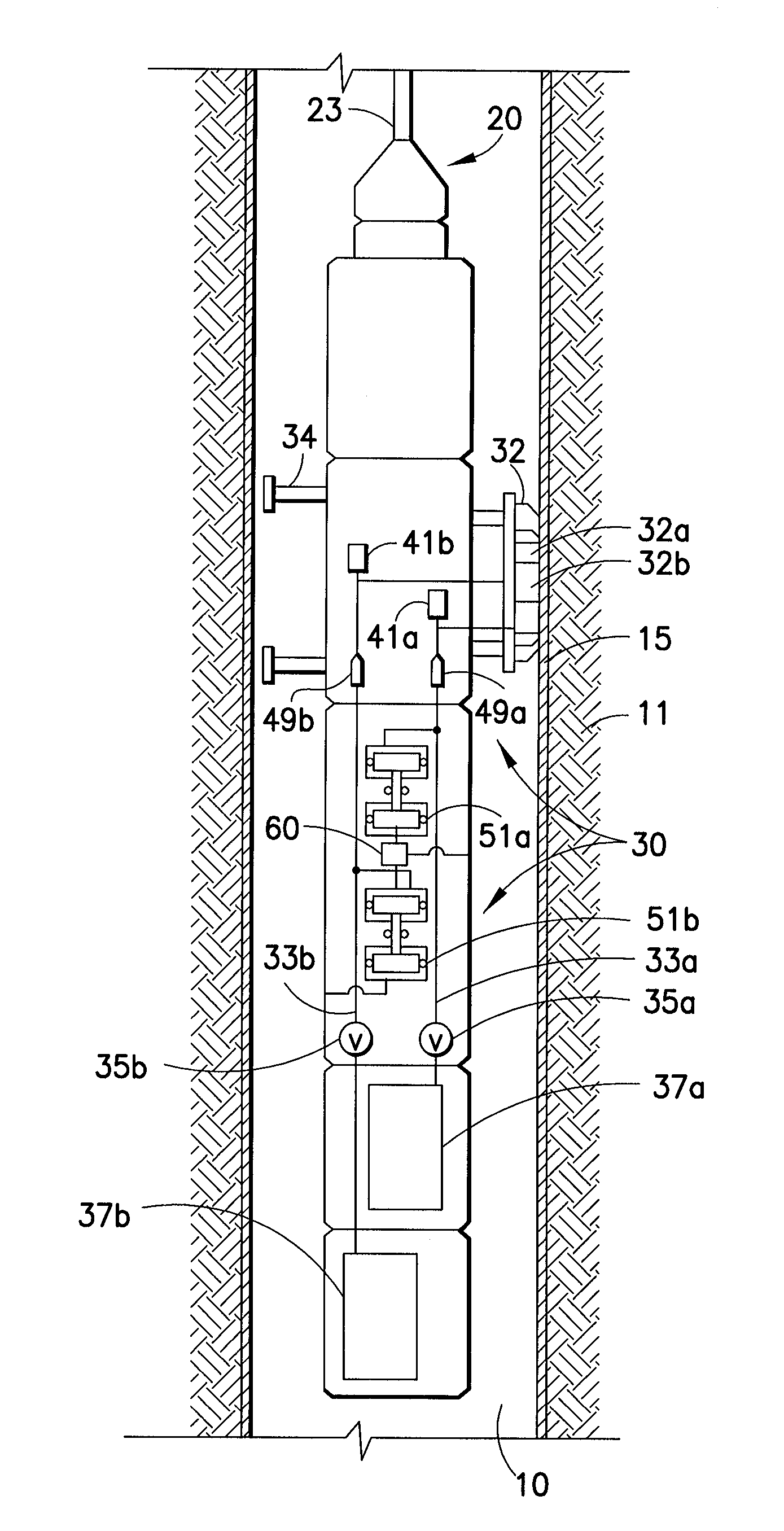
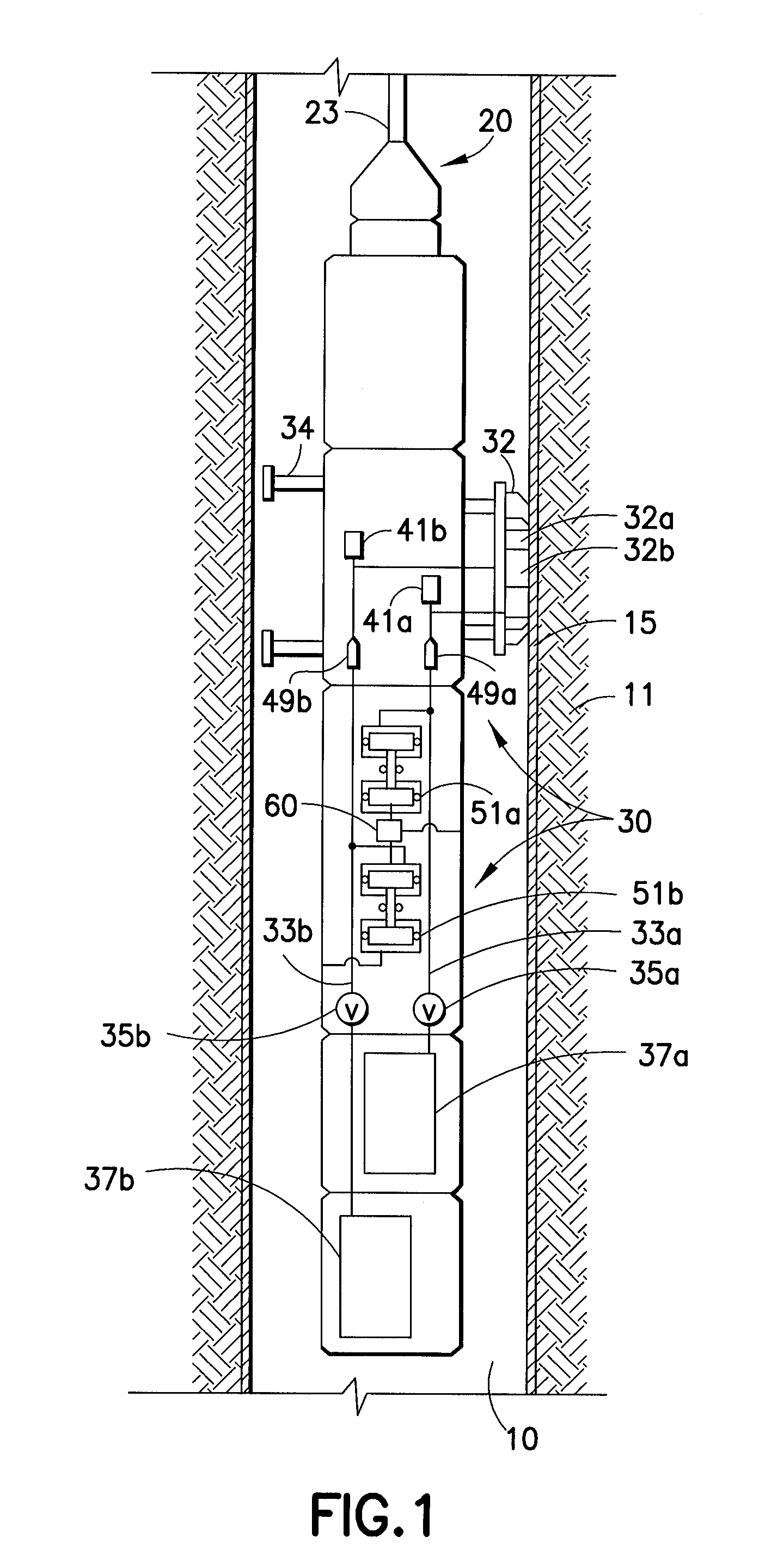
[0024]Turning now to FIG. 1, a borehole 10 is seen traversing a subterranean formation 11. The borehole wall is covered by a mudcake 15. A formation tester tool 20 is seen connected to a wireline 23 which extends from a rig at the surface (not shown). Alternatively, the formation tester tool 20 may be carried on a drillstring.

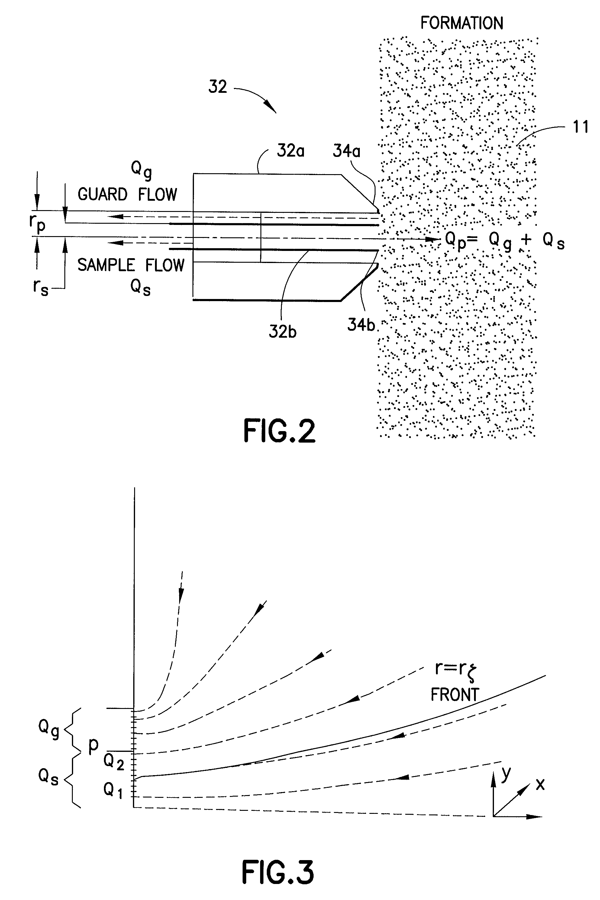
[0025]The formation tester tool 20 is provided with a fluid sampling assembly 30 including a probe 32 (shown in more detail in FIG. 2), and extendable arms 34 or other mechanisms which are used to mechanically push and fix the probe 32 into engagement with the borehole. As seen in FIG. 2, probe 32 includes an outer or guard tube 32a and an inner or sample tube 32b. Each tube is preferably provided with a sharp tip or knife edge, with the sharp tip 34a of the outer tube being slightly forward (preferably between 1 mm and 5 mm forward) the sharp tip 34b of the inner tube. The tubes 32a, 32b are respectively connected by hydraulic flow lines, 33a, 33b, via valves ...


PUM


Abstract

A single probe system is utilized to quickly obtain uncontaminated formation fluid samples. The single probe includes an outer guard tube and an inner sampling tube which is slightly recessed relative to the outer tube such that the pressure at the front face of the probe is substantially uniform. Each tube is coupled to its own pump which controls the flow rate of the fluid moving through that tube. Knowing the size of the sampling tube relative to the size of the outer probe tube, and optionally based on relative viscosities of formation fluids and filtrates, the pumps are caused to generate a particular flow rate ratio through the tubes such that an appropriate pressure is maintained at the front face of the probe and such that the fluid flowing through the sampling tube is substantially uncontaminated.

Description

BACKGROUND OF THE INVENTION[0001]1. Field of the Invention[0002]This invention relates broadly to formation fluid collection. More particularly, this invention relates to a single probe formation tester that permits a relatively quick recovery of formation fluids without contamination caused by borehole fluids.[0003]2. State of the Art[0004]During drilling of a wellbore, a drilling fluid (“mud”) is used to facilitate the drilling process. In order to avoid a blowout of the well, the drilling mud is maintained at a pressure in the wellbore greater than the fluid pressure in the formations surrounding the wellbore. In many instances, the drilling mud is often an oil-based mud (“OBM”). Because of the pressure difference between the wellbore mud and the formations, the drilling fluid penetrates into or invades the formations for varying radial depths (referred to generally as invaded zones) depending upon the types of formation and drilling fluid used. The OBM miscibly mixes with the cr...

Claims


Application Information

Patent Timeline
Patent Type & Authority Patents(United States)
IPC IPC(8): E21B47/08
CPCE21B49/10
Inventor RAMAKRISHNAN, TERIZHANDUR S.
Owner SCHLUMBERGER TECH CORP
Why Eureka
Try Eureka