Railway truck suspension design

Active Publication Date: 2007-09-04
AMSTED RAIL CO INC
View PDF5 Cites 17 Cited by
  • Summary
  • Abstract
  • Description
  • Claims
  • Application Information

AI Technical Summary

Benefits of technology

[0036]Decreasing the reserve capacity of the spring assembly to less than the AAR standard of 1.50, for specific railway cars, meets the need for improved ride quality, increased resistance to suspension bottoming, an

Problems solved by technology

During normal railcar usage or operation, these and other variations can result in wheel-truck oscillations, which may induce the railcar body to bounce, sway, rock or engage in other unacceptable motions.
Wheel-truck movements transferred through the suspension system may reinforce and amplify the uncontrolled motions of the railcar from track variations, which action may result in wheel-truck unloading, and a wheel or wheels of the truck may lift from the track.
In an extreme case, the wheels can elevate and misalign from the track, which enhances the opportunity for a derailment.
All of these motion modes are undesirable and can lead to unacceptable railcar performance, as well as contributing to unsafe operation of the railcar.
Friction shoes dissipate suspension system energy by frictionally damping relative motion between the bolster and sideframe.
However, in a variable rate spring structure, the operating range, or

Method used


Image

  • Railway truck suspension design
  • Railway truck suspension design
  • Railway truck suspension design

Examples


Example

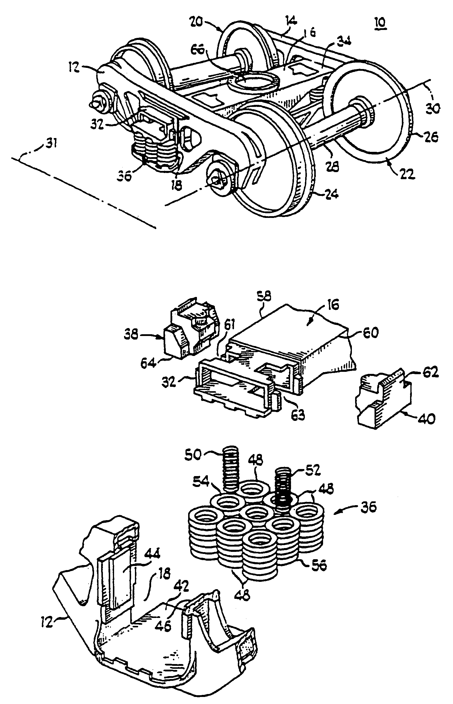
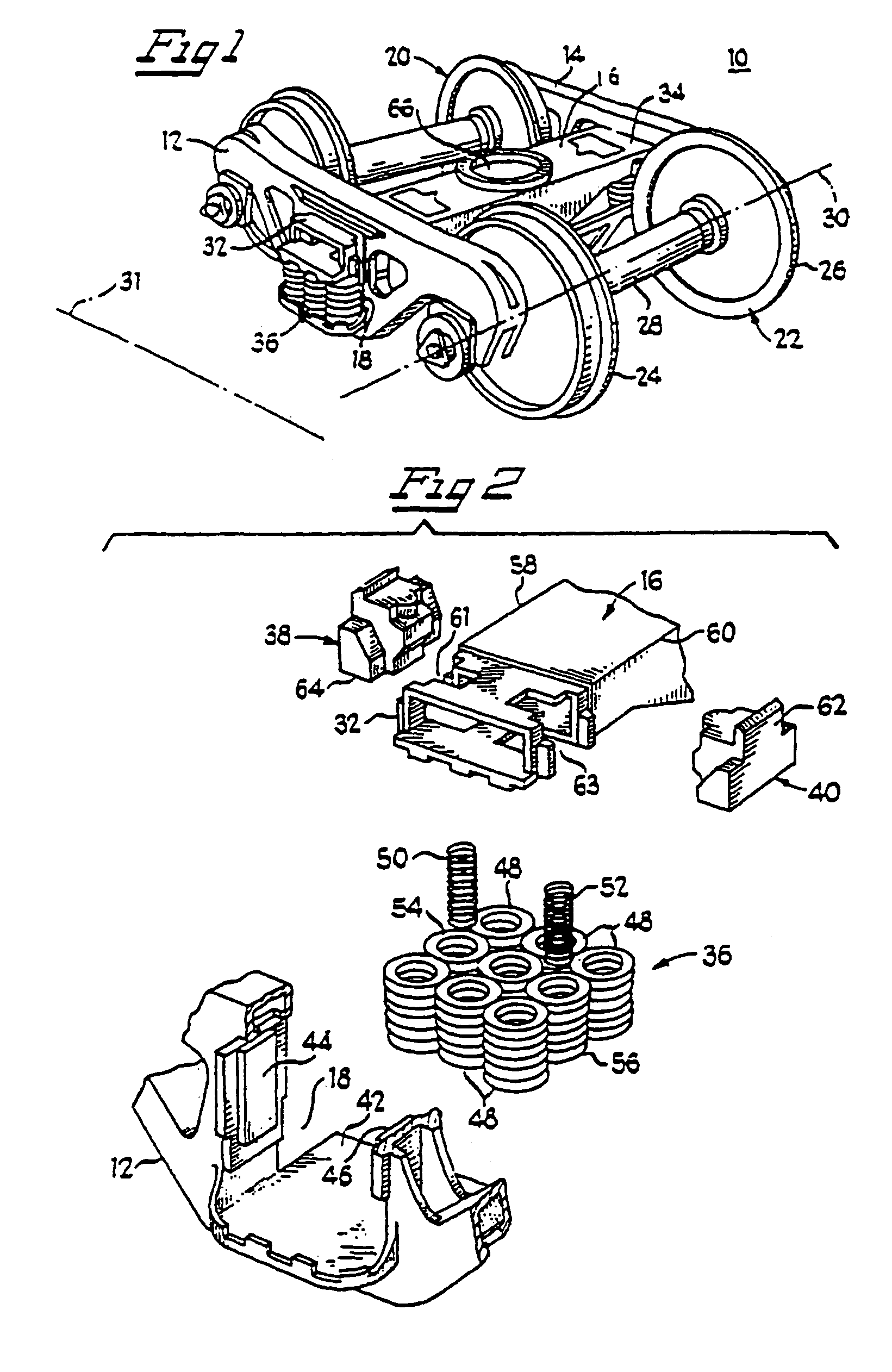
[0076]An exemplary railcar wheel truck assembly 10, as shown in FIG. 1, has a first sideframe 12 and a second sideframe 14, which are arranged in parallel alignment. Transverse bolster 16 couples first and second sideframes 12 and 14 generally at their respective spring windows 18, which are about at the longitudinal midpoint of first and second sideframes 12, 14. First axle and wheel set 20 and second axle and wheel set 22 are positioned at the opposed ends of aligned sideframes 12 and 14. Each of first and second axle and wheel set 20, 22 has an axle axis 30 generally transverse to the longitudinal axis 31 of first and second sideframes 12, 14 and about parallel to bolster 16. Each of first and second wheel sets 20, 22 include wheels 24 and 26 and axle 28 with axle axis 30.

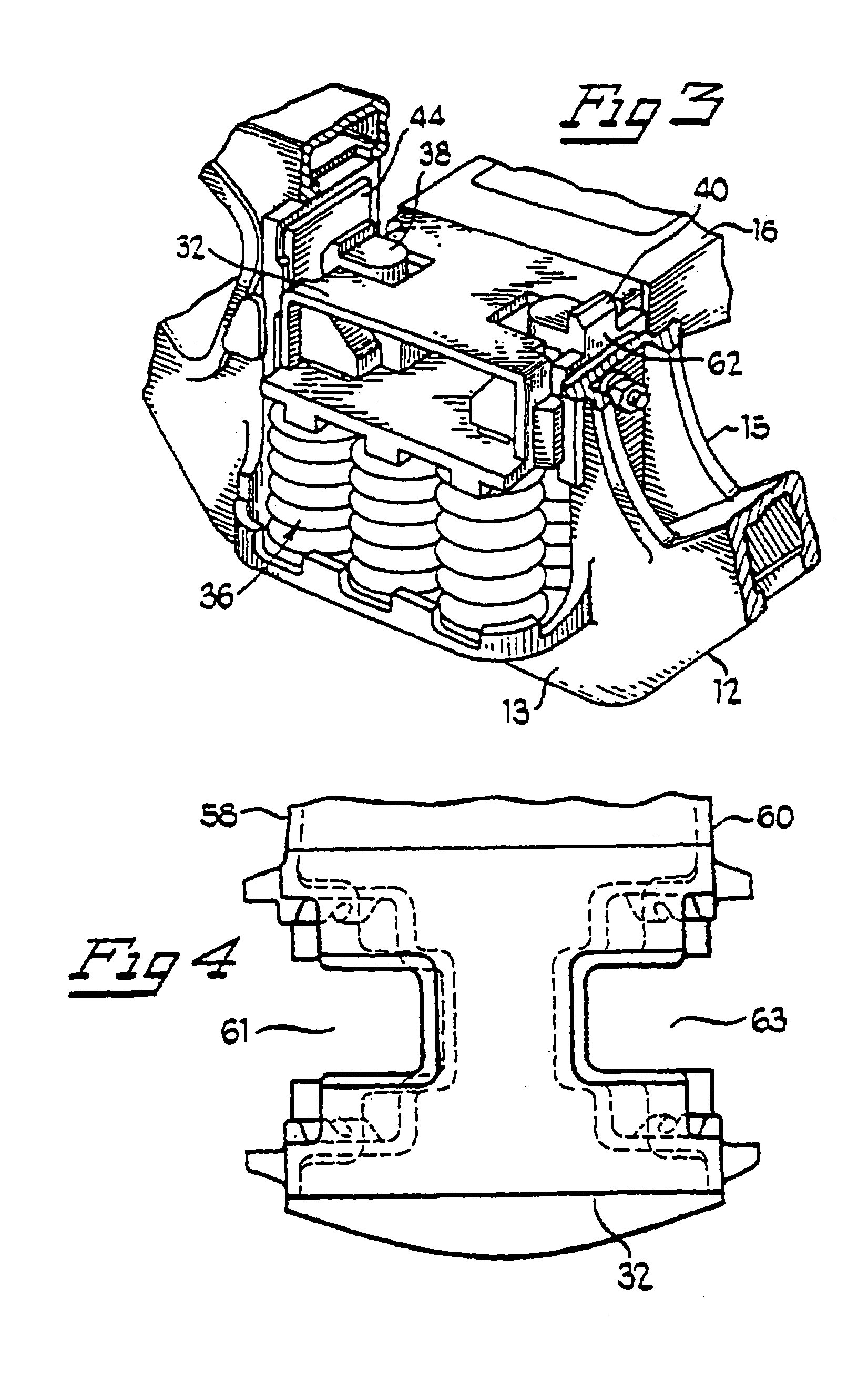
[0077]Bolster 16 has first end 32 and second end 34, which respectively extend through windows 18 of first and second sideframes 12 and 14 in FIG. 1. Window 18, bolster end 32, spring group 36, first friction sh...


PUM


Abstract

A tuned spring group with load springs, control springs, and a frictional damping arrangement for a railcar truck assembly provides better ride quality, increased resistance to suspension bottoming, and increased hunting threshold speed of a railroad car. Specifically, this tuned damping and suspension arrangement provides a spring group reserve capacity of less than 1.50. Spring assemblies for different car types are tuned such that a reserve ratio less than 1.50 may be achieved. By reducing the spring assembly reserve capacity for a railcar and truck of a standard weight and configuration to less than 1.50, an unexpected result of a decrease in maximum vertical acceleration as the railcar truck assembly approaches a speed of 55 miles per hour is achieved. The decrease in vertical acceleration allows for improved ride quality, increased resistance to suspension bottoming and increased hunting threshold speed of the railcar.

Description

CROSS-REFERENCE TO RELATED APPLICATIONS[0001]This is a non-provisional application claiming priority under 35 U.S.C. §119(e) to U.S. Provisional Application Ser. No. 60 / 482,133, filed on Jun. 25, 2003, incorporated herein by reference in its entiretyBACKGROUND OF THE INVENTION[0002]1. Field of Invention[0003]The present invention relates to an improved suspension system in a wheel-truck assembly for supporting a railcar that allows improved ride quality, increased resistance to suspension bottoming, and increased hunting threshold speed of a railroad car.[0004]2. Description of Related Art[0005]The opposed ends of a railcar body are commonly supported on spaced-apart wheel-truck assemblies for travel along a railway track. A standard railcar wheel-truck assembly generally has a laterally spaced pair of sideframes which are longitudinally operable along the tracks and parallel to the longitudinal axis of the railcar. A bolster, which is transversely positioned to the longitudinal dir...

Claims


Application Information

Patent Timeline
IPC IPC(8): B61F3/00B61F5/00B61F5/04B61F5/06B61F5/10B61F5/12B61F5/14B61F5/30
CPCB61F5/301
Inventor PERSHWITZ, JULIUS I.BERG, THOMAS R.
Owner AMSTED RAIL CO INC
Why Eureka
Try Eureka