
Septic system remediation method and apparatus

Active Publication Date: 2007-09-04
AERO STREAM
View PDF16 Cites 10 Cited by
  • Summary
  • Abstract
  • Description
  • Claims
  • Application Information

AI Technical Summary

Benefits of technology

[0015]Accordingly, the present invention provides an apparatus and a method for the remediation of failing private onsite wastewater treatment systems, such systems being comprised of a septic tank having an inlet and an outlet, in some cases, a second septic tank or pumping chamber having an inlet and an outlet and a seepage pit, drywell, absorption field or a above grade mound system having an inlet and a plurality of outlets wherein effluent drains from the inlet to the outlet. The apparatus, in its most simple form, comprises (a) a positive pressure pump having an out

Problems solved by technology

Such systems are typically found in relatively sparsely populated areas not otherwise serviced by municipal waste water systems.
Replacement of any septic system component that may be required to deal with remediation of the entire system can be extremely expensive.
First, as designed, solid wastes precipitate out of the flow to the bottom of the septic tank.
Unfortunately, this is not always the case.
While aerobic bacteria typically break down solid wastes more quickly than anaerobic bacteria, they are ineffective at breaking down sludge, or the solid layer at the bottom of the septic tank, because there is no oxygen present in that layer.
Due to increased installation and operating costs, aerobic systems that would otherwise eliminate this sludge layer are not favored for home use.
Unfortunately, the bio-mat layer can grow to a thickness where it almost completely, or almost completely, impedes absorption.
While there are many ways in which septic systems can fail, two of the most likely modes of failure include the creation and thickening of a bio-mat layer at the absorption field component of the system due to the decomposition of solids within the effluent.
For example, when the rate of decomposition caused by the anaerobic bacteria is incapable of keeping up with rate of solids draining into the system, the septic tank fills with sludge.
As the sludge level gets higher, the scum level at the top of the tank takes up more space.
And if too much of the absorption field is plugged by scum and solids, the effluent will actually back up in the absorption area and cause muddy spots in the area above the absorption field.
This is a sign that the absorption field has failed, an extremely malodorous and unsightly condition.
As alluded to earlier, replacement of soil absorption systems is frighteningly costly and heavily regulated by states, counties and municipalities due to the threat that malfunctioning systems pose to the groundwater.
Replacement systems are very expensive, with the actual expense depending on the condition of other components in the septic system.
Some owners choose to convert their existing passive system to an active system, an even more costly endeavor.
Above grade systems also have operating and maintenance expenses and those are even greater than passive systems.
Holding tanks are frequently the option of last resort as they are also expensive and need to be regularly pumped by a commercial contractor.
Unfortunately, aerobic bacteria also require the introduction of oxygen into the waste stream.

Method used


Image

  • Septic system remediation method and apparatus
  • Septic system remediation method and apparatus
  • Septic system remediation method and apparatus

Examples


Embodiment Construction

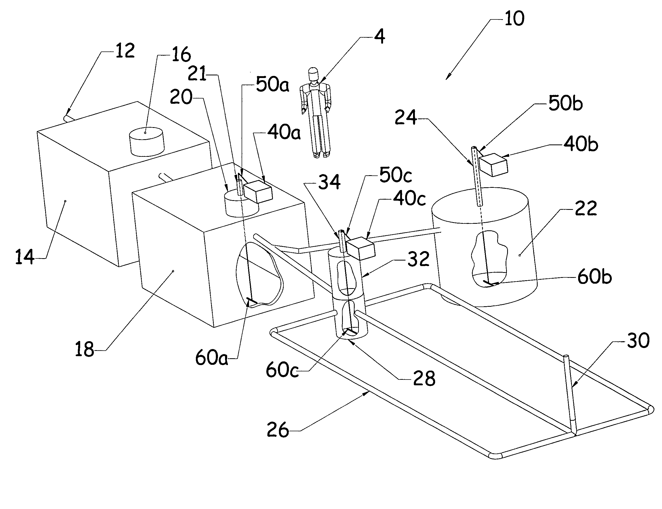
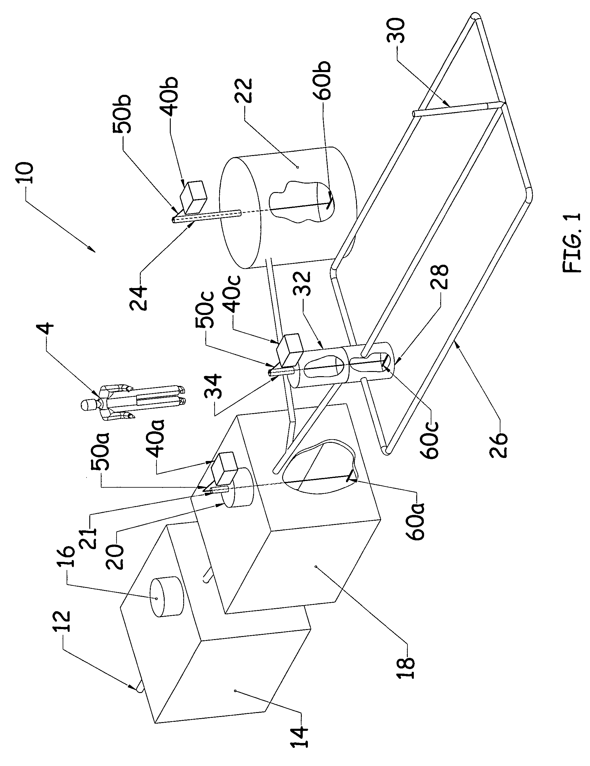
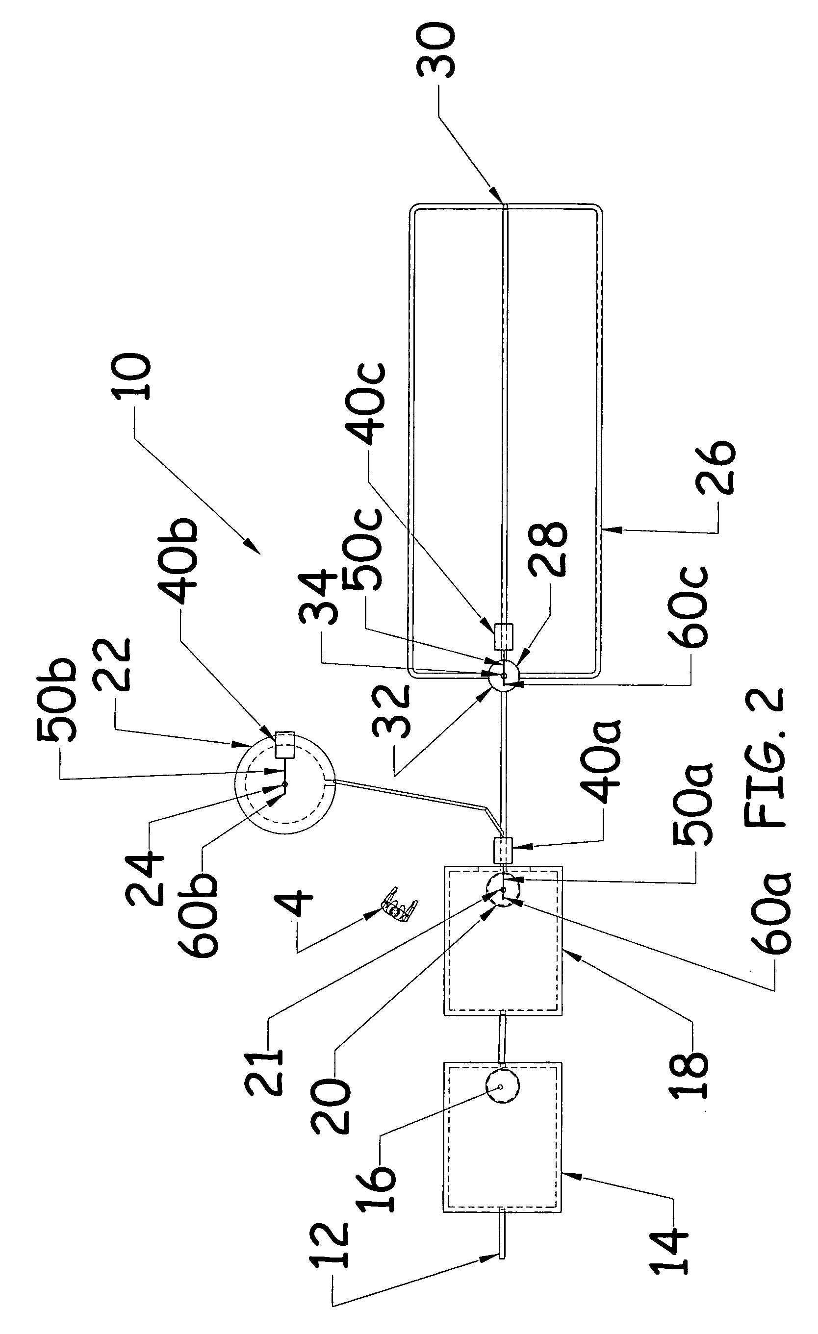
[0023]Reference is now made to the drawings wherein like numbers refer to like elements throughout. FIG. 1 illustrates a septic system, generally identified 10, with which the apparatus and method of the present invention is intended to be used. It is to be understood, however, that the precise configuration of the system is not a limitation of the present invention and could assume any number of sizes and layouts. The septic system 10 shown is for illustration purposes only. A six foot tall man 4 is included for relative size reference as well.

[0024]As shown in FIG. 3, the septic system 10 lies, for the most part, below earth grade 2. The system 10 includes a pipe 12 leading from a home or building (not shown) which pipe 12 is connected to a first septic tank 14. The first tank 14 may or may not have a vented cover. As shown, the first tank 14 includes a riser 16. The first tank 14 is, in turn, connected to a second tank 18. This second tank 18 may or may not have a vented cover as...


PUM

PropertyMeasurementUnit
Pressureaaaaaaaaaa
Areaaaaaaaaaaa

Abstract

An apparatus and a method for the remediation of failing wastewater treatment systems, such systems being comprised of one or more septic tanks and a seepage pit, drywell, absorption field or an above grade mound system having an inlet and a plurality of outlets wherein effluent drains from the inlet to the outlet, comprises a positive pressure pump having an output, a tube having a first end and a second end, the first end being attachable to the pump output, and an air stone attachable to the second tube end. The pump is used to deliver air through the tube to the air stone. As much tube as is required is used to allow the air stone to be introduced into almost any portion of the wastewater treatment system so as to introduce air into the effluent to allow aerobic bacteria to proliferate. The apparatus could also include a plurality of such pumps, tubes and air stones, and in many combinations. The method comprises introducing oxygen to the bio-mat, introducing live aerobic bacteria to the bio-mat, monitoring the level of effluent in the absorption field or dry well, and stopping the introduction of air to the effluent when the bio-mat is sufficiently reduced or made permeable. The method could also introduce live anaerobic bacteria to the treated area after remediation equipment is removed.

Description

[0001]This application claims the benefit and priority of U.S. Provisional Application No. 60 / 442,446 filed Jan. 25, 2003.FIELD OF THE INVENTION[0002]This invention relates generally to septic systems and to the components that make up such systems. More particularly, it relates to a method and to an apparatus for remediating the formation of a bio-mat that can occur in the absorption field component of a private on-site wastewater treatment system.BACKGROUND OF THE INVENTION[0003]Septic systems and septic system components are well known in the art. Such systems are typically found in relatively sparsely populated areas not otherwise serviced by municipal waste water systems. The purpose of a septic system is to dispose of the wastewater that is generated by the occupants of a home or other building in such a manner that surrounding soils can be used to disperse the wastewater without causing an adverse effect on ground water and, in turn, on public health and the environment in ge...

Claims


Application Information

Patent Timeline
IPC IPC(8): C02F3/00C02F3/20C02F3/28C02F3/30
CPCC02F3/286C02F3/30C02F3/20Y02W10/10
Inventor HOLT, KARL K.
Owner AERO STREAM
Learn More