
Magnetic spring and actuators with multiple equilibrium positions

Active Publication Date: 2007-09-04
LAUNCHPOINT TECH
View PDF16 Cites 47 Cited by
  • Summary
  • Abstract
  • Description
  • Claims
  • Application Information

AI Technical Summary

Benefits of technology

[0011]Arrays of magnets are configured to create linear or rotary magnetic springs with multiple equilibrium points. Some of the equilibrium points are stable, while others are unstable. No mechanical contact is required between moving and stationary elements of the magnetic springs, resulting in a virtually unlimited lifetime. The magnetic springs can be utilized in conjunction with low force electromagnetic actuat

Problems solved by technology

Some of the equilibrium points are stable, while others are unstable.

Method used


Image

  • Magnetic spring and actuators with multiple equilibrium positions
  • Magnetic spring and actuators with multiple equilibrium positions
  • Magnetic spring and actuators with multiple equilibrium positions

Examples


first embodiment

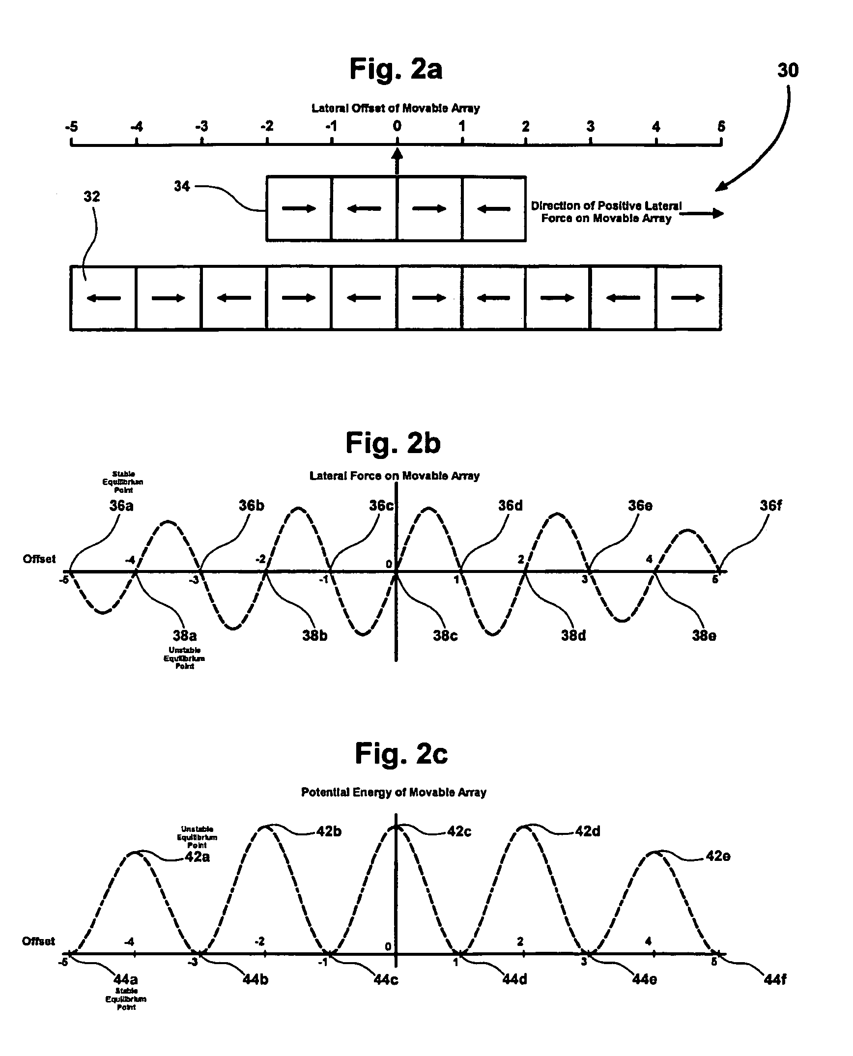
[0045]With reference to the drawings, FIG. 2a shows an arrangement of magnetic dipoles 30 according to the invention. Here, a row of dipoles 32 is configured in a fixed or stationary array with each dipole rotated 180 degrees with respect to adjacent magnets. The poles depicted are horizontal but other angles would be acceptable as long as the rotation requirement is met. Such rotation requirement is utilized within Halbach arrays as discussed within U.S. Pat. No. 6,374,746 issued to Fiske on Apr. 23, 2002, U.S. Pat. No. 6,684,794 issued to Fiske et al. on Feb. 3, 2004, and U.S. patent application Ser. No. 10 / 412,082 filed on Apr. 10, 2003 by Fiske et al. and published on Oct. 16, 2003 as US Patent Application Publication No. 2003-0192449, each document of which is herein incorporated by reference. Accordingly, arrays 32 and 34 of FIG. 2a can be considered as Halbach arrays with a rotation increment of 180 degrees.

[0046]A movable array of magnets 34, using a similar configuration of...

fourth embodiment

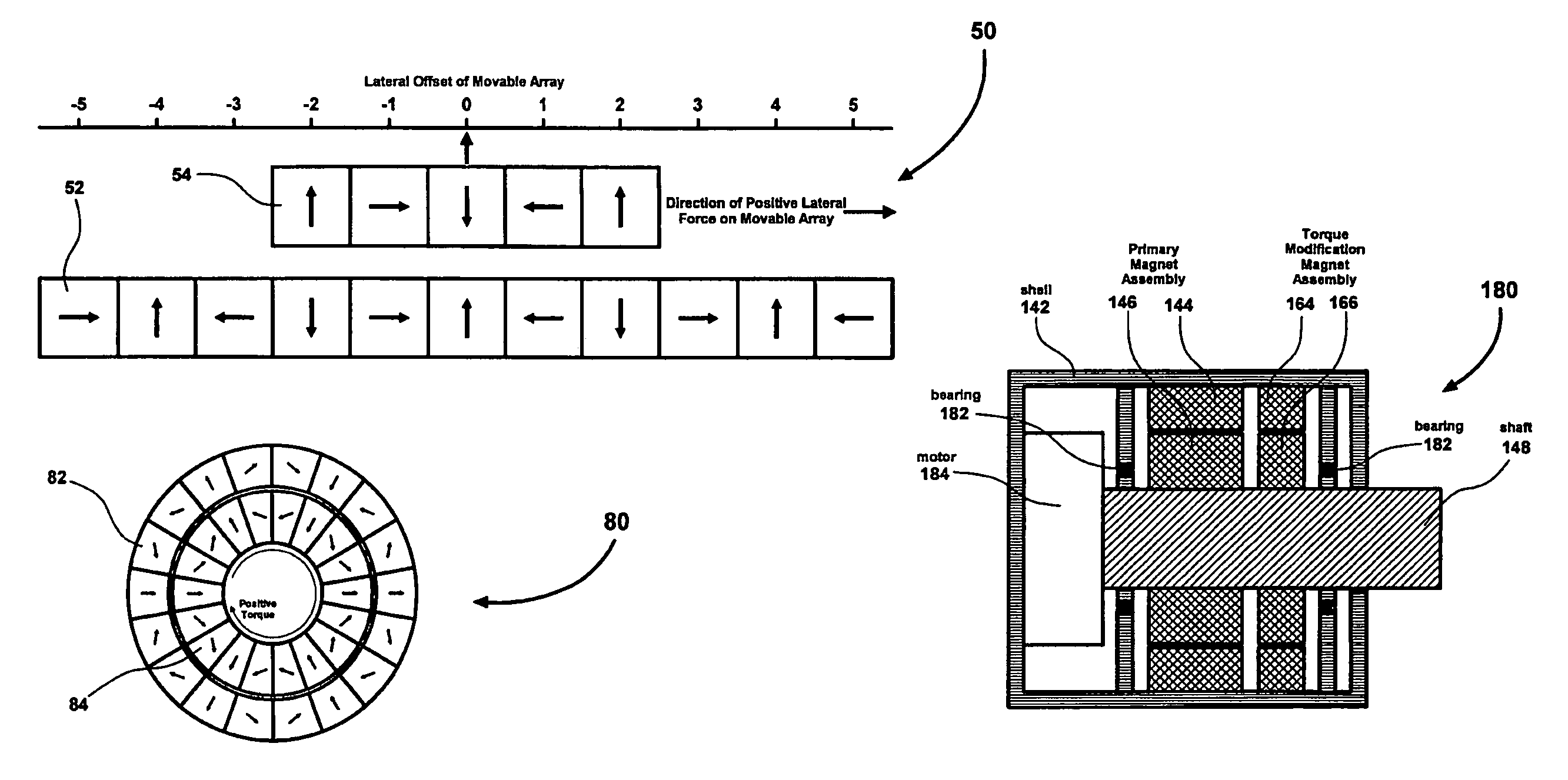
[0049]FIG. 5a shows an arrangement of magnets 80 similar to that of FIG. 4a but modified according to the invention. Here, the magnets are configured as concentric Halbach arrays, in which the direction of magnetization of each magnet in outer array 82 is rotated clockwise as the array is traversed clockwise. The direction of magnetization in inner array 84 is rotated counterclockwise as the array is traversed clockwise. Again, this has the effect of focusing the field produced by each array toward the opposing array to produce higher torque per unit of mass of magnet material. Arrays 82 and 84 shown in FIG. 5a use six magnets per wavelength and three wavelengths per array for a total of 18 magnets per array. However, it should be readily understood that more or less magnets may be used to produce shorter or longer wavelengths without straying from the intended scope of the present invention. Arrays 62 and 64 of FIG. 4a can be considered Halbach arrays with a rotation increment of 1...


PUM


Abstract

Arrays of magnets configured to create linear or rotary magnetic springs with multiple equilibrium points. Some of the equilibrium points are stable, while others are unstable. No mechanical contact is required between moving and stationary elements of the magnetic springs, resulting in a virtually unlimited lifetime. The magnetic springs can be utilized in conjunction with low force electromagnetic actuators to implement multi-step linear or rotary actuators with high force, very short movement time between unstable equilibrium points, and with near-zero holding power required to maintain actuator position at any unstable equilibrium point. Specific applications that embody the present invention may include, but are not limited to, optical filters, linear valves, or any mechanism that would benefit from an efficient magnetic spring.

Description

CROSS-REFERENCE TO RELATED APPLICATIONS[0001]This application claims priority from U.S. Provisional Patent Applications Nos. 60 / 535,803 filed on Jan. 13, 2004 and 60 / 543,865 filed on Feb. 10, 2004.FIELD OF THE INVENTION[0002]This invention relates to apparatus and methods for creating linear or rotary magnetic springs with multiple equilibrium positions. More specifically, such magnetic springs can form multi-position linear or rotary actuators.BACKGROUND OF THE INVENTION[0003]Electric motors of various types are commonly used to rapidly move an object linearly from one stationary position to another or to rotate an object from one stationary angular position to another by accelerating and then decelerating the object. The motor converts electric energy into the kinetic energy of the moving object during acceleration, and then brakes the object by converting that kinetic energy into another form such as heat during the deceleration. However, in some applications such motors are inca...

Claims


Application Information

Patent Timeline
IPC IPC(8): H02K21/00H02K1/17H02K35/02H02K41/02
CPCF16F6/005H02K26/00H02K49/106
Inventor PADEN, BRADLEY EVANCHEN, CHENFISKE, ORLO JAMES
Owner LAUNCHPOINT TECH
Learn More