
Method of manufacturing microlens, microlens, optical film, screen for projection, and projector system

a manufacturing method and technology for microlens, applied in the field of manufacturing microlens, microlens, optical films, screens for projection and projector systems, can solve the problems of high cost of manufacturing lenses adaptable to screens for large-scale, difficult machine and facility scale-up, and cost reduction, etc., to achieve flexible manufacturing and reduce cost

Inactive Publication Date: 2007-09-04
SEIKO EPSON CORP
View PDF15 Cites 12 Cited by
  • Summary
  • Abstract
  • Description
  • Claims
  • Application Information

AI Technical Summary

Benefits of technology

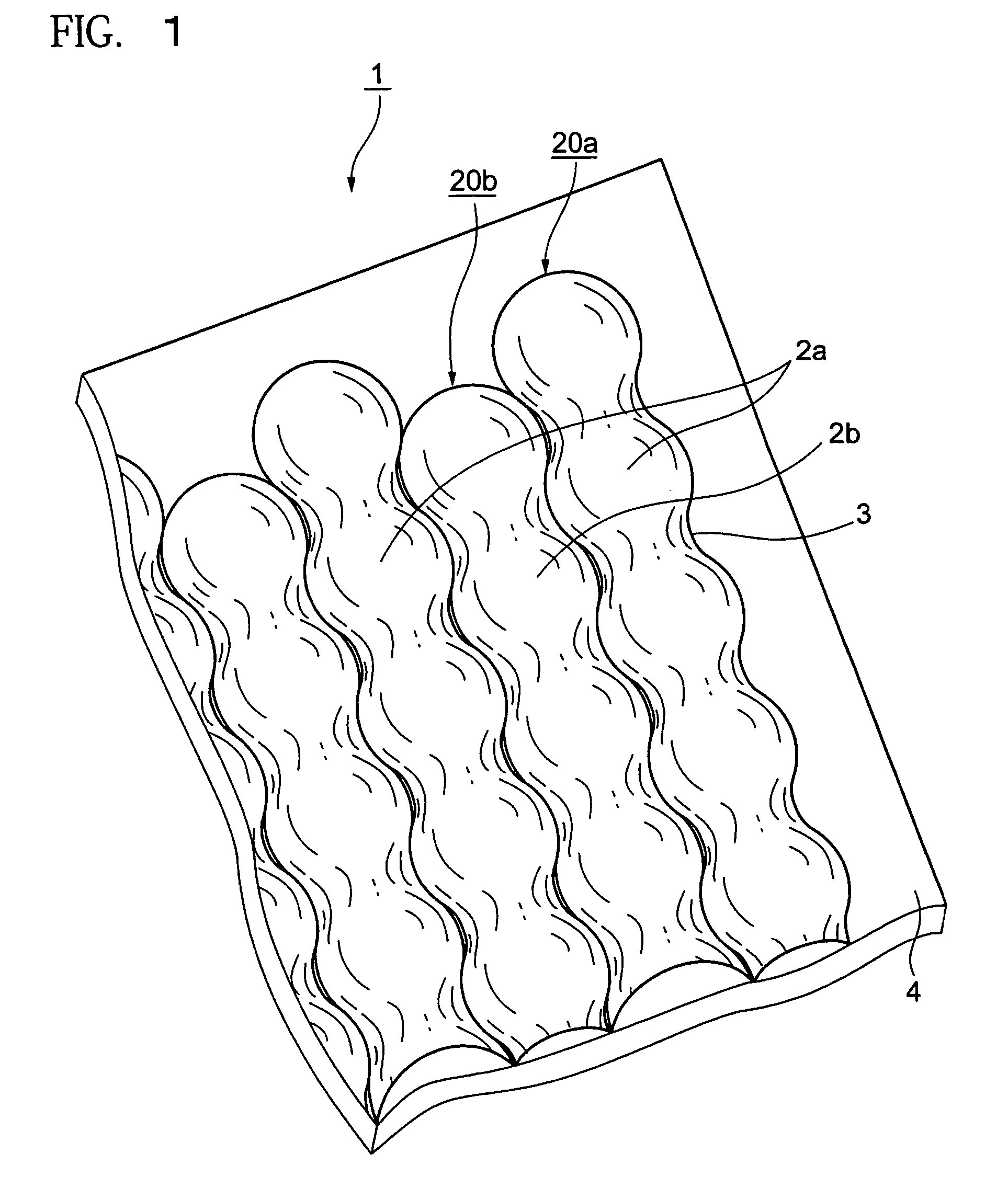
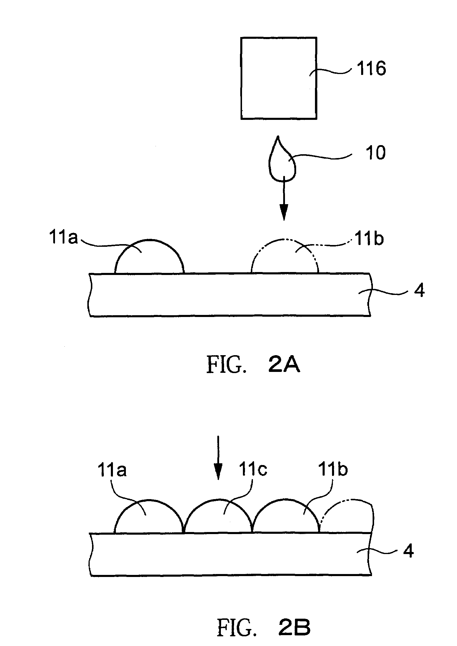
[0012]According to this exemplary manufacturing method, by forming the lens portions in the first process and the third process separately, the lens portions between each row can be reduced or prevented from being closely coupled more than necessary and the shape of the lens portions can be reduced or prevented from collapsing.
[0014]According to this structure, formation of the lens portions are not only divided twice, material type of the droplet to be discharged is also changed. Accordingly, each lens portions can be reduced or prevented from being closely coupled more than necessary and the lens portions having a more accurate shape can be manufactured.
[0016]According to these structures, enhancement of light diffusibility of the lens portions can be obtained by mixing and dispersing the light diffusive fine particles in the light transmissive resin. Furthermore, by carrying out liquid repellent processing on the surface of the substrate, the droplet discharged on the substrate becomes a more rounded shape, and a function as a lens becomes better.
[0018]In these structures, the lens portions are formed on the entire surface of the substrate, and a microlens can be obtained which can evenly diffuse light in wide directions by an assembly of the lens portions. In addition, in order to increase performance of the microlens, light diffusibility is enhanced by using the light transmissive resin in which the light diffusive particles are mixed for formation of the lens portions. Better convex shape of the lens portions are formed by carrying out the liquid repellent processing on the surface of the substrate.
[0022]According to this structure, the screen for projection evenly displayed projected images without inconsistency, can be obtained by using the optical film having the microlens for the lenticular sheet.
[0025]According to the manufacturing method of a microlens of exemplary embodiments of the present invention, the various sized microlens can be flexibly manufactured by a droplet discharging device without using expensive dies or the like. Further, loss of material such as a gate portion when the die is used, can be eliminated, and at the same time the cost can be reduced. Furthermore, a microlens having uniform light diffusibility as a surface of the entire substrate can be manufactured by forming a plurality of lens portions on the entire surface of the substrate.

Problems solved by technology

However, in related art manufacturing methods of the lens portions (cylindrical lens 80) of the lenticular sheet that are manufactured by injection mold using a die, it is difficult in scale-up of machine and facility.
Further, there is a high cost to manufacture a lens adaptable to the screen for large-sized projection, for example, of 50 inches.
Furthermore, in order to respond to demand on the lens portions of the various sized lenticular sheets, many dies have to be stored, which lead to a burden on storage space, financial aspects, or the like.
Furthermore, the cylindrical lens 80 of the lens portions of the lenticular sheet diffuse light in the longitudinal direction and the perpendicular direction, however, diffuses little light in the other directions, thus visibility in all directions may not be provided.

Method used


Image

  • Method of manufacturing microlens, microlens, optical film, screen for projection, and projector system
  • Method of manufacturing microlens, microlens, optical film, screen for projection, and projector system
  • Method of manufacturing microlens, microlens, optical film, screen for projection, and projector system

Examples


Embodiment Construction

[0037]A manufacturing method of a microlens according to exemplary embodiments of the present invention is described with reference to the attached drawings.

[0038]At first, as an example of the microlens being used effectively, a screen for projection used in a projector system is schematically described. As shown in FIG. 7, a projector system 70 includes a projector 71 and a screen 30 for projection (hereinafter, referred to as screen), and the projector 71 includes a light source 72 such as mercury lamp, a lens group 75 to guide light from the light source 72 to a liquid crystal light bulb including a liquid crystal panel, the liquid crystal light bulb (light modulating device) 73 modulating light passing through the liquid crystal panel and sending out the light as an image to be projected, and an imaging lens (imaging optical system) 74 imaging the image of light passed through the liquid crystal light bulb 73 on to the screen 30. In the projector system 70 of such a structure, ...


PUM

PropertyMeasurementUnit
diameteraaaaaaaaaa
volumeaaaaaaaaaa
volumeaaaaaaaaaa

Abstract

Exemplary embodiments of the present invention provide an optimal manufacturing method of a microlens to diffuse light. According to exemplary embodiments, a manufacturing method of microlens includes forming a generally convex shaped lens portions made from a light transmissive resin on a substrate having light transmissivity, and curing the lens portions, forming the lens portions being a process in which a plurality of the lens portions are formed so as to be coupled on the substrate.

Description

BACKGROUND OF THE INVENTION[0001]1. Field of Invention[0002]The present invention relates to a method of manufacturing a microlens, a microlens, an optical film, a screen for projection and a projector system.[0003]2. Description of Related Art[0004]The related art includes lens portions of a lenticular sheet included in a screen for projection, as shown in FIG. 11. The lens portions are in a shape in which a plurality of half-cylindrical shaped cylindrical lenses 80 are disposed on a transparent substrate 4 so that their longitudinal directions are parallel. The lenses have a function to diffuse light to the longitudinal direction and perpendicular direction. For this reason, the lens portions of the lenticular sheet have an effect to enlarge the visible range of the image or the like projected on the screen. Specifically, the effect is to enhance or improve visibility from directions other than the front of the screen. For example, the shape is shown inrelated art document Japanes...

Claims


Application Information

Patent Timeline
Patent Type & Authority Patents(United States)
IPC IPC(8): G02B27/10B29D11/00G02B3/00G02B3/08B29C41/20B29C41/36B29C67/02G03B21/62
CPCB29C41/20B29C41/36B29C67/02G03B21/625G02B3/0012G02B3/0043B29D11/00365G02B1/041
Inventor HASEI, HIRONORI
Owner SEIKO EPSON CORP
Learn More