Objective lens drive having optical axis adjustment function

Inactive Publication Date: 2007-09-04
TEAC CORP
View PDF16 Cites 3 Cited by
  • Summary
  • Abstract
  • Description
  • Claims
  • Application Information

AI Technical Summary

Benefits of technology

[0008]The invention provides an apparatus capable of adjusting an inclination (tilt) of an opt

Problems solved by technology

Provision of the piezoelectric element raises a problem

Method used


Image

  • Objective lens drive having optical axis adjustment function
  • Objective lens drive having optical axis adjustment function
  • Objective lens drive having optical axis adjustment function

Examples


Embodiment Construction

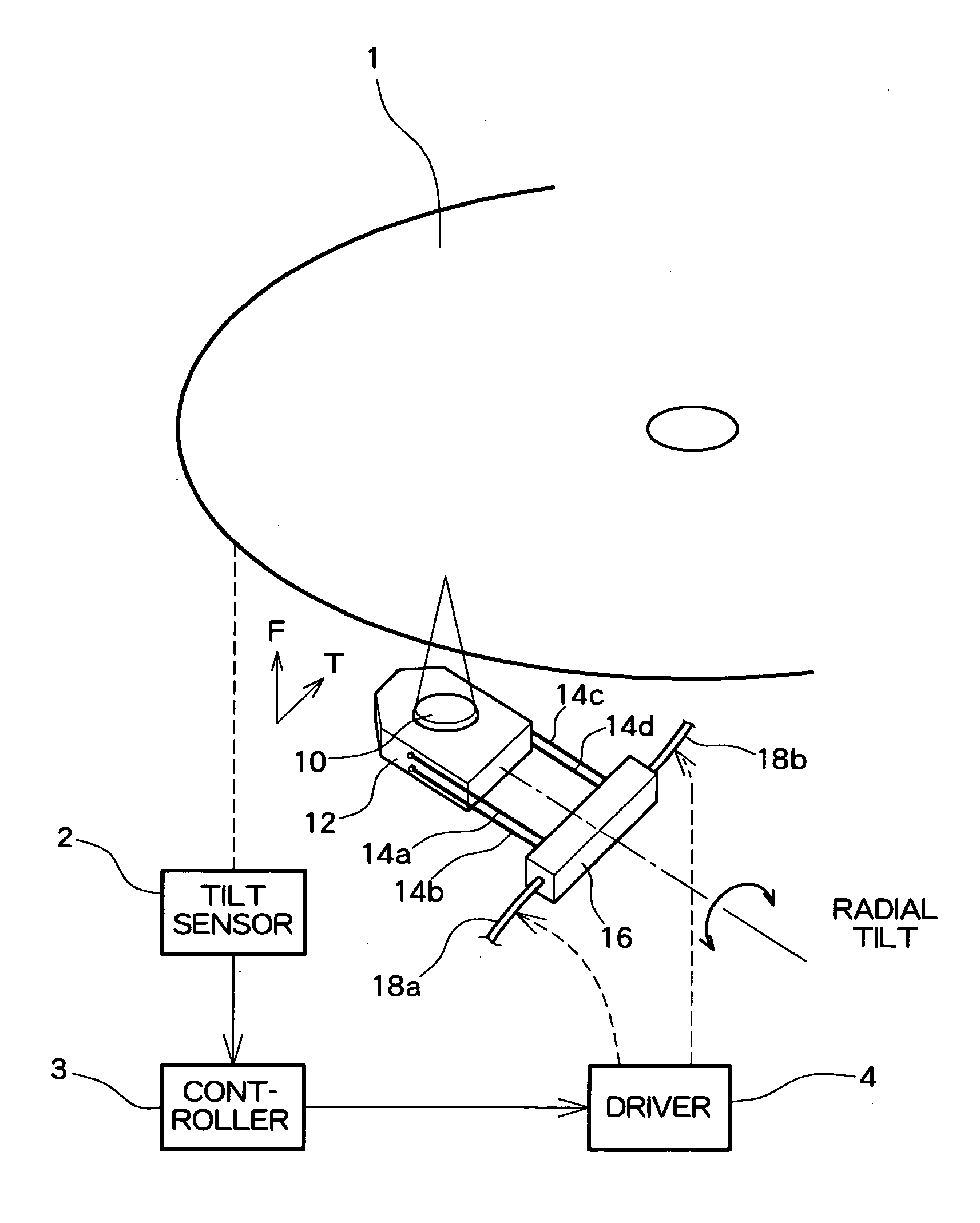
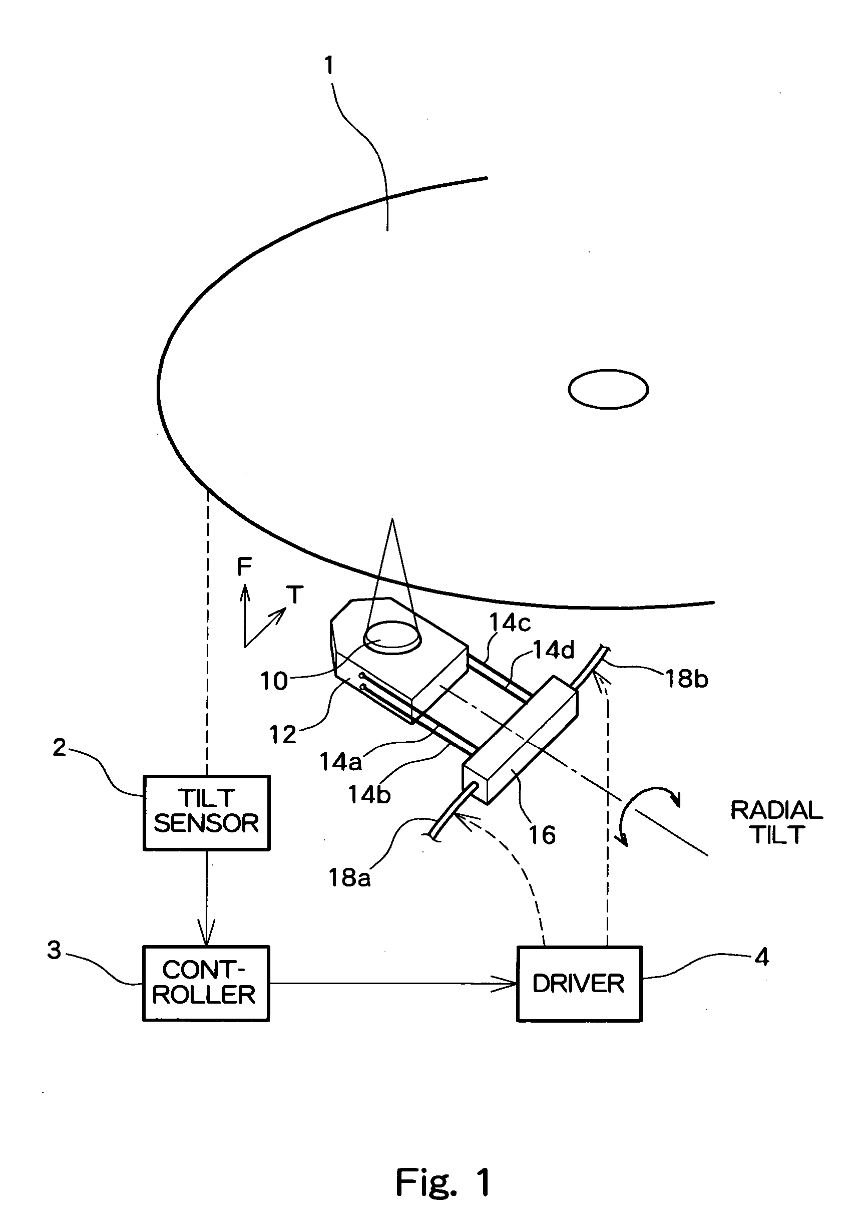
[0019]Embodiments of the invention will be described hereinbelow by reference to the drawings. A case where an optical axis of an optical pickup is adjusted in a radial direction will now be described by means of taking, as an example, an optical pickup to be incorporated into an optical disk drive such as a CD drive or a DVD drive.

[0020]FIG. 1 shows the overall configuration of the optical pickup of the embodiment. An optical disk 1 is rotatably driven by a spindle motor. An objective lens 10 is disposed so as to oppose the optical disk 1. The objective lens 10 is supported by a lens holder 12, and the lens holder 12 is supported by four suspensions 14a, 14b, 14c, and 14d in a cantilever fashion. Specifically, one end of each of the suspensions 14a, 14b is fixed to a left-side surface of the lens holder 12, and the other end of each of the suspensions 14a, 14b is fixed to a suspension holder 16. One end of each of the suspensions 14c, 14d is fixed to a right-side surface of the len...


PUM


Abstract

An objective lens drive having an optical axis adjustment function. An objective lens is supported by a lens holder, and the lens holder is supported on a suspension holder by way of a suspension. The suspension holder is supported so as to be rotatable about an axis extending in a direction in which the suspension extends, whereby the suspension holder is supported laterally by means of multilayer piezoelectric elements. When a drive voltage is applied to the multilayer piezoelectric elements, the piezoelectric elements are displaced vertically, whereupon the suspension holder is rotated about the axis, to thus adjust the optical axis of the objective lens.

Description

BACKGROUND OF THE INVENTION[0001]1. Field of the Invention[0002]The invention relates to an objective lens drive, and more particularly, to a mechanism for adjusting the tilt of an optical axis of an objective lens.[0003]2. Description of the Related Art[0004]An apparatus for adjusting the inclination (tilt) of an optical axis of an objective lens with respect to a disk in an optical pickup has already been known.[0005]In an optical pickup, one end of a suspension is fixed to a portion of a base, and a lens holder is fixed to the other end of the suspension, thus supporting the lens holder in a cantilever fashion. A magnet or a coil is provided on the lens holder, and the objective lens is driven in focusing and tracking directions by means of electromagnetic interaction developing between the lens holder and a magnetic circuit disposed on the base side of the optical pickup. In order to adjust the optical axis of the objective lens, there has already been known a configuration in w...

Claims


Application Information

Patent Timeline
IPC IPC(8): G11B7/00G11B7/09G11B7/095
CPCG11B7/0933G11B7/0956G11B7/0937
Inventor NARAOKA, KOJI
Owner TEAC CORP
Why Eureka
Try Eureka