
Linearized filter band equipment and processes

a filter band and linearization technology, applied in the field of filtering devices, can solve the problems of not providing sharp cutoff, not providing physical realizable filters, and not achieving the desired frequency respons

Active Publication Date: 2007-09-04
INMUSIC BRANDS
View PDF2 Cites 56 Cited by
  • Summary
  • Abstract
  • Description
  • Claims
  • Application Information

AI Technical Summary

Benefits of technology

[0012]In one or more various alternate embodiments, related systems include but are not limited to circuitry and/or programming for effecting the foregoing-referenced method embodiments; the circuit...

Problems solved by technology

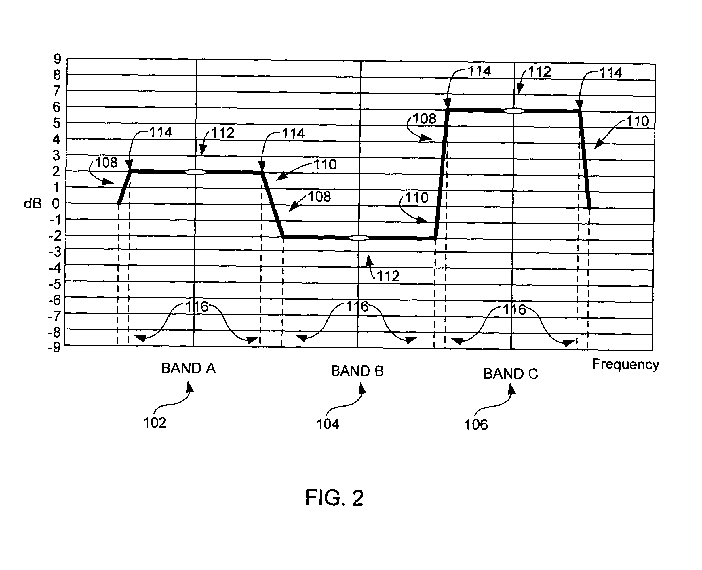
Those skilled in the art will appreciate that, unfortunately, physically realizable filters do not tend to provide the desired response of the “ideal” filters shown in FIG. 2.
The fact that physically realizable filters do not provide sharp cutoff allows the energy from one frequency band of the graphic equalizer to bleed into the other frequency bands of the graphic equalizer.
As can be seen, such interference tends to be additive, and thus gives rise to a resultant aggregate frequency response 120 which is not at all in keeping with the desired frequency response.
However, as will be appreciated by those having ordinary skill in the art, both the behavior of the individual filters as well as the interactions between filter bleeds, tends to be highly nonlinear and / or unpredictable.
The effect of this is that it is extremely difficult to use known techniques to alleviate the interference problems, so in practice the desired theoretical approach is typically not achieved.
One drawback of the method disclosed by Lane, and other related-art techniques, is that Lane tends to work with fixed Q value filters.
Lane's, and other related-art techniques, also do not recognize that non-linearity of interactions between filters having fixed Q values varies dependent upon selected cut-boost levels.

Method used


Image

  • Linearized filter band equipment and processes
  • Linearized filter band equipment and processes
  • Linearized filter band equipment and processes

Examples


Embodiment Construction

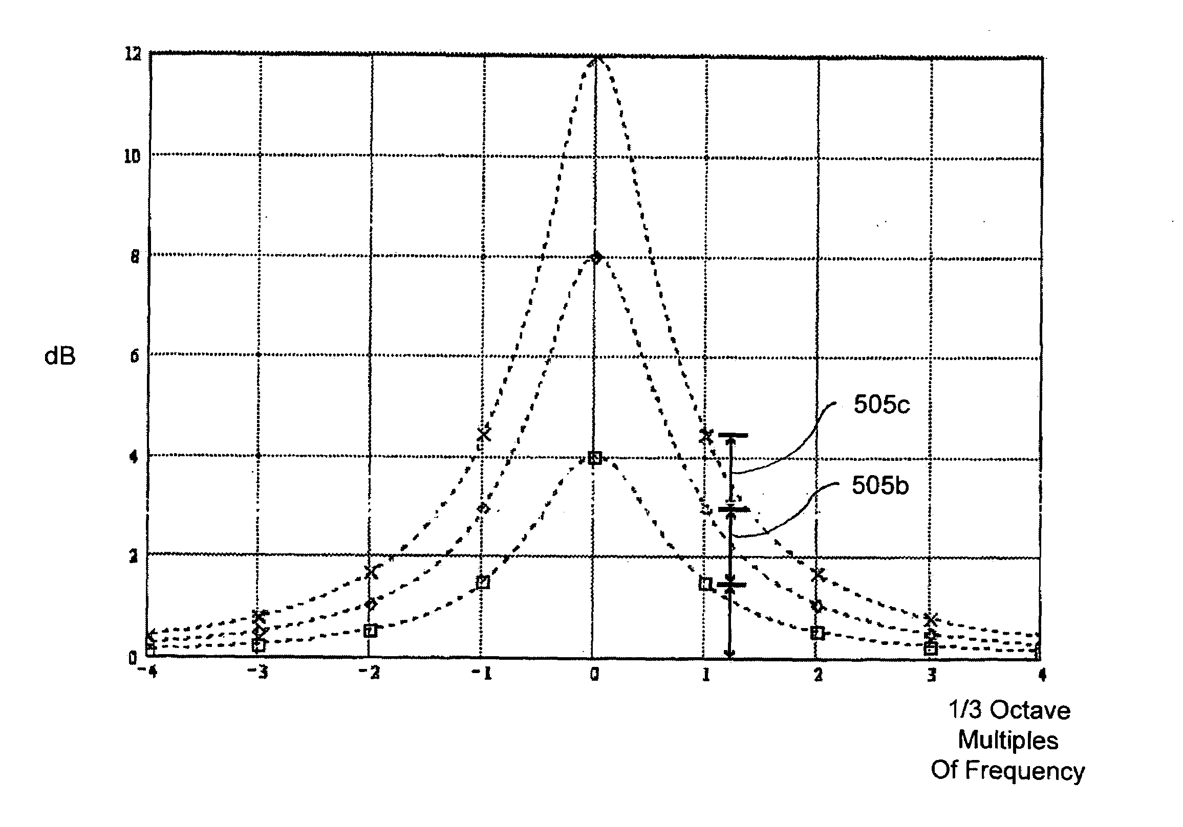
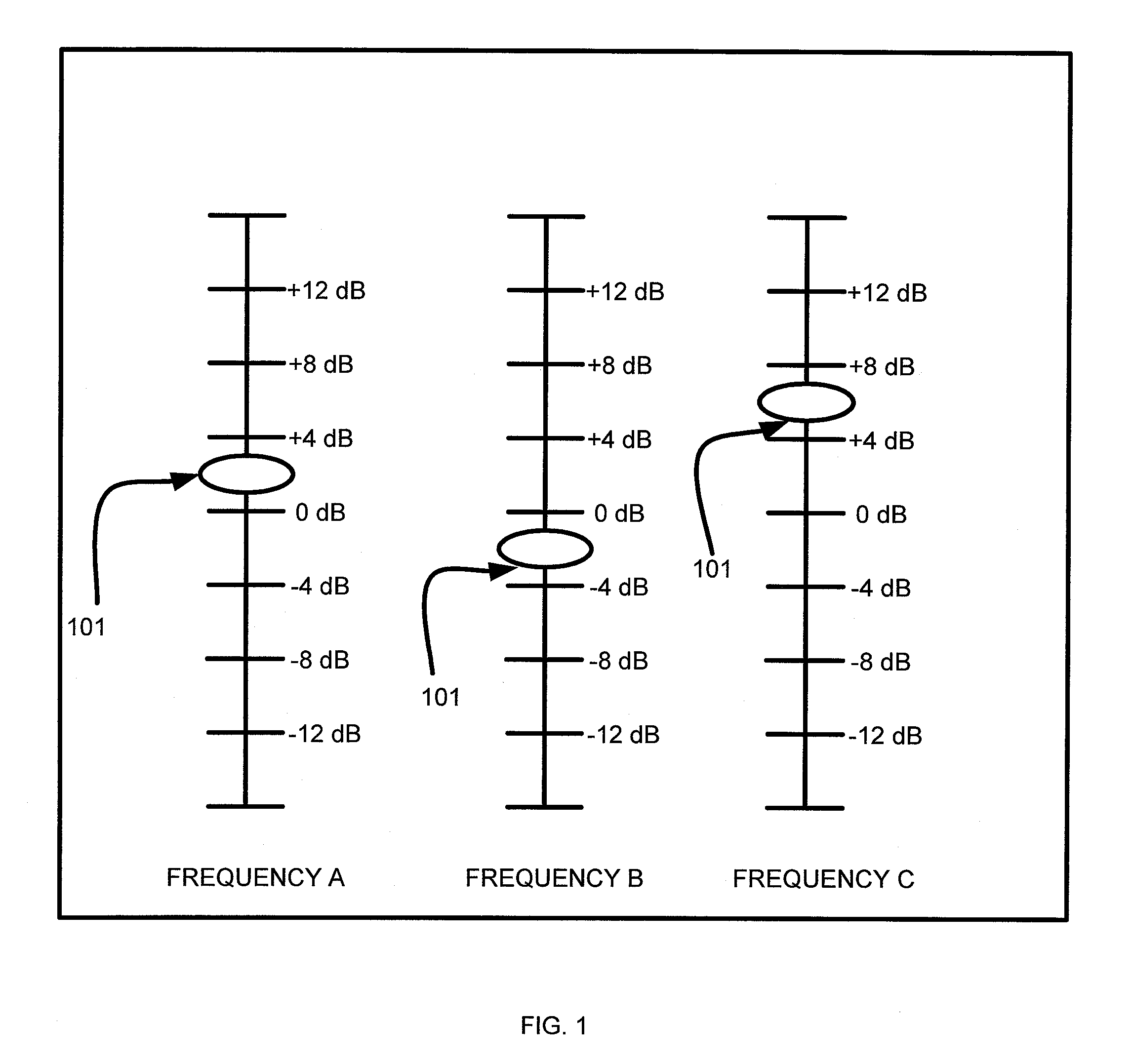
[0029]With reference now to FIG. 4A, a preferred method for idealizing signal passband filters in accordance with the principles of the invention is generally indicated at reference numeral 400. FIG. 4A shows a high level logic flowchart of that process. Method step 500 depicts the start of the process. Method step 502 illustrates selecting filter Q values sufficient to approximately “linearize” the interactions between at least two bandpass filters (e.g., the three filters A, B and C shown and described in relation to graphic equalizer 100). Selecting Q values sufficient to approximately “linearize” interactions between filters consists of choosing, for each individual filter considered in isolation, a series of Q values dependent upon preselected cut or boost levels (e.g., 2, 4, or 6 dB, etc.). The Q values are chosen such that, when each individual filter is excited by a signal, and the cut or boost level of each individual filter is then increased or decreased in a linear fashio...


PUM


Abstract

A method for use with equipment having filters, the method characterized by multiplying a matrix having a specified cut-boost setting of a filter of a graphic equalizer by a correction matrix to create a matrix having a corrected cut-boost setting of the filter of the graphic equalizer; adjusting an actual cut-boost setting of the filter of the graphic equalizer to be substantially equal to the corrected cut-boost setting of the filter of the graphic equalizer; and configuring the filter to have a Q value substantially equal to a linearizing Q value. In addition to the foregoing, other method embodiments are described in the claims, drawings, and text forming a part of the present application. In one or more various embodiments, related systems include but are not limited to circuitry and / or programming for effecting the foregoing-referenced method embodiments; the circuitry and / or programming can be virtually any combination of hardware, software, and / or firmware configured to effect the foregoing-referenced method embodiments depending upon the design choices of the system designer.

Description

FIELD OF THE INVENTION[0001]The present invention relates, in general, to filtering devices. More specifically, the present invention is related to digital signal processing filters and / or analog filters.BACKGROUND OF THE INVENTION[0002]Filtering devices allow for direct selection or suppression of frequency components of electrical signals. Those having ordinary skill in the art will appreciate that, for any particular signal, techniques exist which allow the signal to be approximated by a weighted sum of periodic signals (e.g., sine waves and / or cosine waves which repeat themselves within defined time periods). Each periodic signal in the sum has a certain frequency (inversely related to the time period required for the signal to repeat). The weighted periodic signals which are summed to approximate the analog signal may be referred to as the “frequency components” of the signal. One type of filtering device is known in the art as a “graphic equalizer,” since it graphically illust...

Claims


Application Information

Patent Timeline
IPC IPC(8): H03G5/00G06F15/00H03G5/02H03G5/06H03G9/00H03G9/06H04B15/00
CPCH03G5/005H03G5/025
Inventor MILLER, RAYMOND S.
Owner INMUSIC BRANDS
Learn More