Fiber optic storing and dispensing apparatus

a technology for fiber optic cables and storage devices, applied in the direction of optics, instruments, optical light guides, etc., can solve the problems of affecting the transmission ability of optical signals, damaging the cable, and undesirable storage of fiber optic cables in plastic bags

Active Publication Date: 2007-09-04
FIBER OPTIC PROTECTION SYST
View PDF3 Cites 125 Cited by
  • Summary
  • Abstract
  • Description
  • Claims
  • Application Information

AI Technical Summary

Benefits of technology

[0010]The grooves are formed by axially spaced apart side-by-side flanges, one of which is common to both grooves. An intermediary portion of cable passes from the primary groove in the spool to the secondary groove via a lateral passage adjacent the center of the spool and is guided in its transition between the grooves in such manner as to avoid kinking, twisting, or otherwise damaging the cable.
[0012]The casing preferably includes a pivoted door which may be opened and closed so as to enable that portion of the cable wound about the secondary spool groove to be accessed conveniently. When the door is closed, all of the parts within the casing, including both of the cable sections wound on the spool, will be protected by the casing against damage from external forces.

Problems solved by technology

The storage of a fiber optic cable in a flimsy plastic bag is undesirable because of the susceptibility to damage of such cable while accommodated in such bag.
Manual uncoiling of the cable frequently causes the cable to become twisted or kinked, whereas manual recoiling of the cable subjects it to the possibility that it will be wound about a radius less than the minimum bending radius, thereby physically damaging the cable and adversely affect its ability to transmit an optical signal without undue attenuation.
In those instances in which the test set and a fiber optic jumper cable are shipped or stored in the same container, the cable is exposed to the possibility of damage by the test equipment itself.
The current practice, therefore, requires the selection of a length of cable, which almost always is greater than the distance to be spanned, thereby resulting in excessive sagging of the cable between its ends and requiring the cable, after use, to be recoiled by hand resulting in uncertain bending radii and increasing the risk of damaging the cable.

Method used


Image

  • Fiber optic storing and dispensing apparatus
  • Fiber optic storing and dispensing apparatus
  • Fiber optic storing and dispensing apparatus

Examples


Embodiment Construction

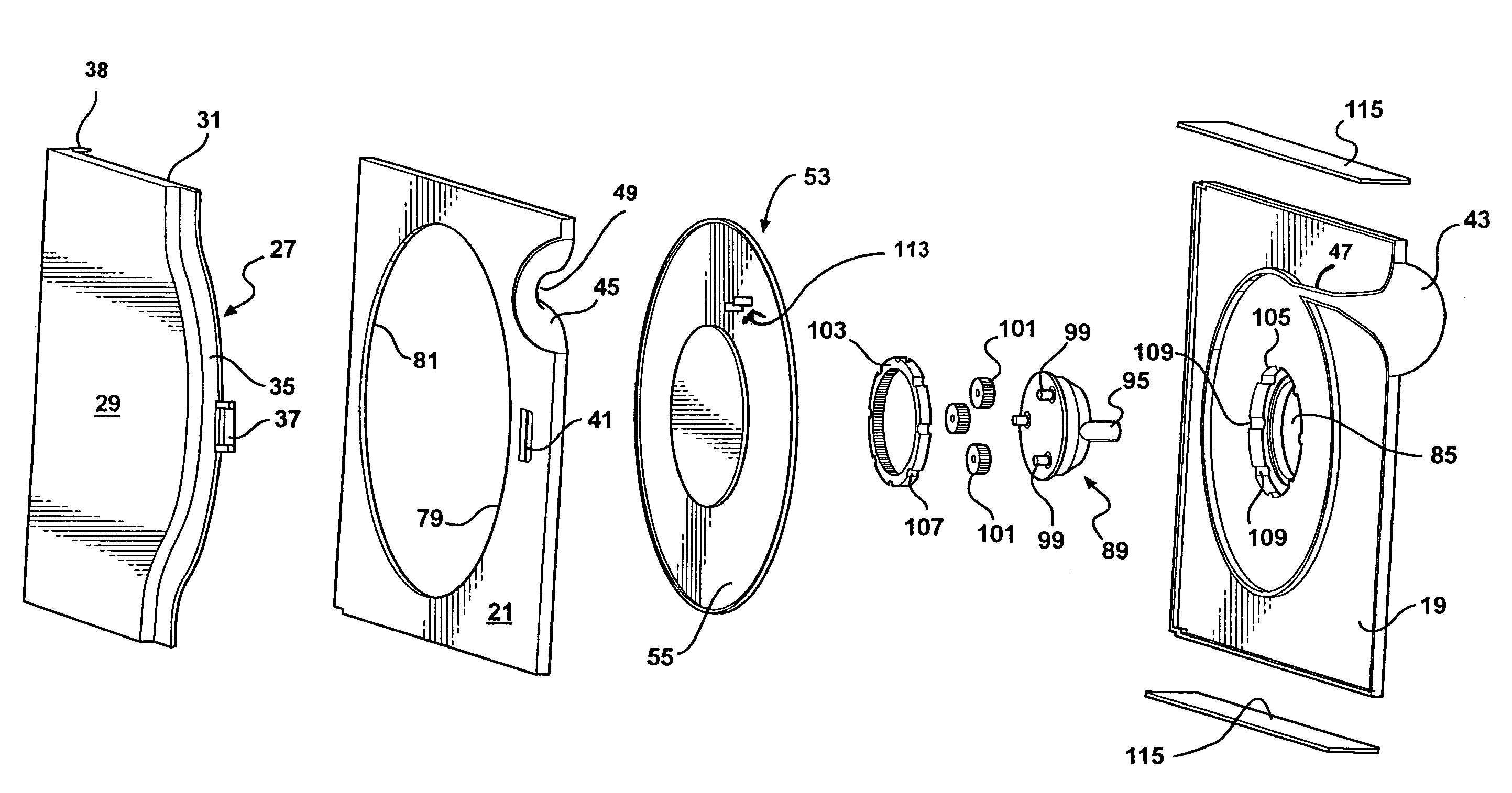
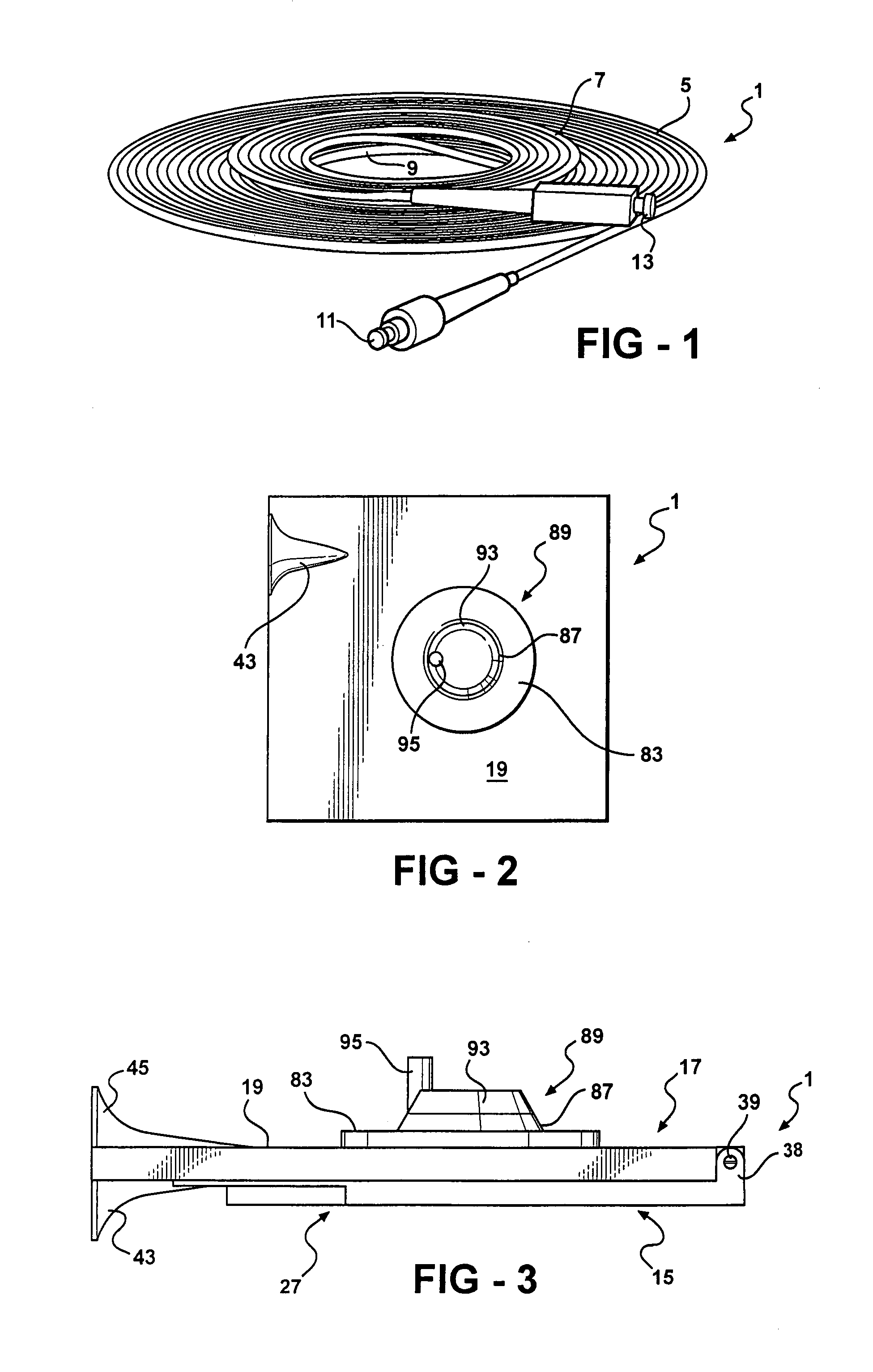
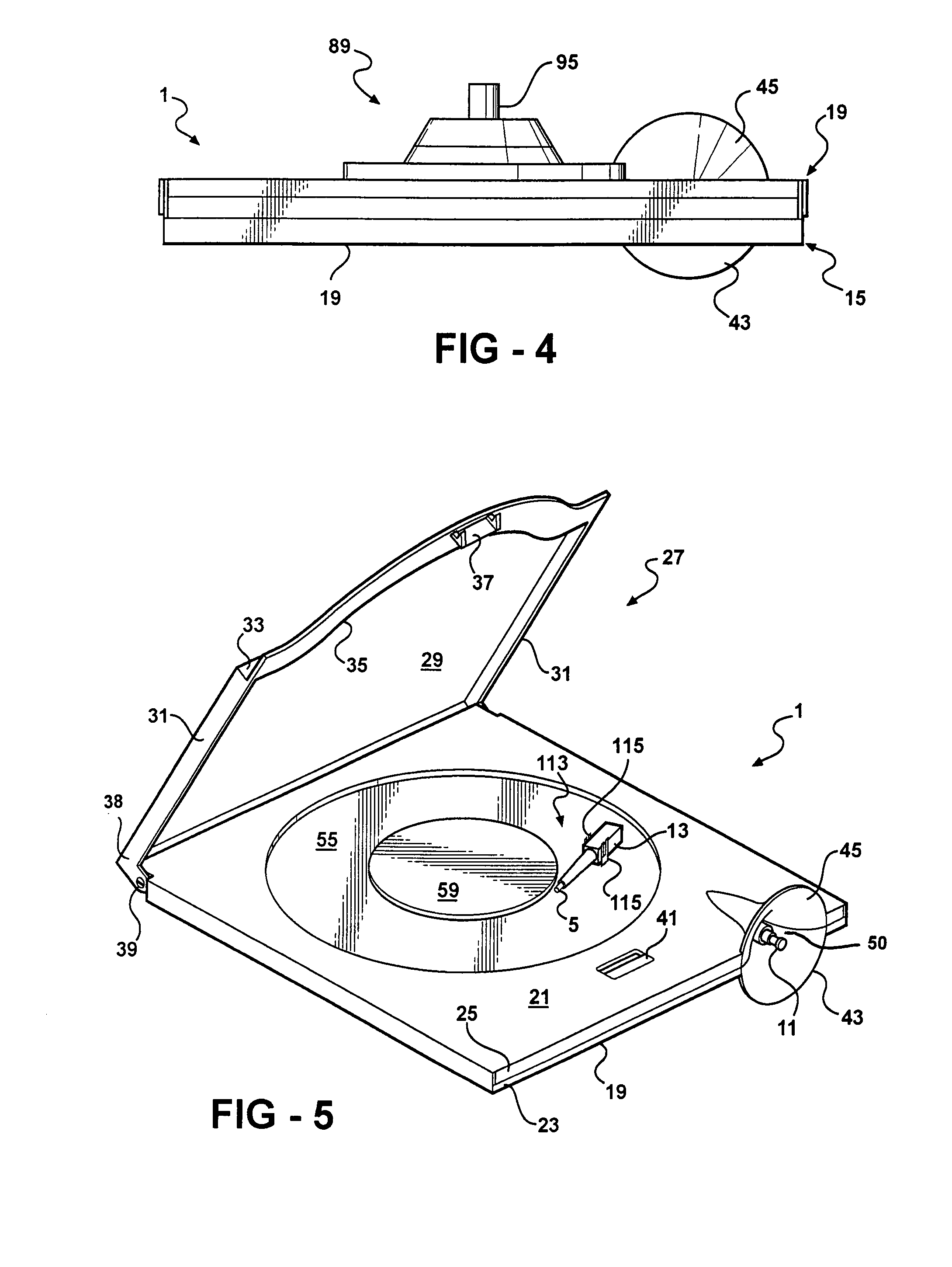
[0024]Apparatus constructed in accordance with the presently preferred embodiment of the invention comprises a casing 1 formed from rigid plastic material, such as polycarbonate or that used in the manufacture of so-called jewel cases for compact discs and the like. The casing is adapted to contain a selected length of coilable material, such as a conventional, cladded fiber optic cable 3. As shown in FIG. 1 the cable 3 is a single, unitary cable having two coil sections 5 and 7 each of which is wound about a radius at least as great as the minimum bending radius of the cable. The section 5 has a length greater than that of the section 7. The longer section 5 sometimes will be referred to herein as the primary section and the shorter section 7 as the secondary section. The cable includes an integral intermediate section 9 which forms a transition between the sections 5 and 7. At one free end of the cable 3 is fixed a conventional fitting or connector 11 and at the opposite

[0025]The ...


PUM

PropertyMeasurementUnit
radiusaaaaaaaaaa
lengthaaaaaaaaaa
widthaaaaaaaaaa

Abstract

Storage and dispensing apparatus for use with a unitary length of coilable fiber optic cable having a minimum bending radius, such apparatus having a casing within which is journaled a rotatable spool having two grooves in which relatively long and relatively short lengths of the cable may be coiled. One end of the cable is coupled to a connector that is releasably retained on the spool for rotation therewith. The opposite end of the cable is joined to a connector which is extendible from and retractable into the casing in which the spool is journaled. The casing is formed of rigid plastic material which protects the cable against damage from externally applied forces. No part of the cable within the casing is subject to being bent about a radius less than the minimum bending radius.

Description

[0001]This invention relates to apparatus for storing and dispensing coilable material, such as a fiber optic cable, in and from a protective casing.BACKGROUND OF THE INVENTION[0002]When installing, testing, maintaining, or tuning all ranges of fiber optic networks it is necessary to use various test sets. A test set ordinarily will include one or more fiber optic jumper cables for verifying the integrity of signal flow through various parts of the fiber optic circuit. The length of the fiber optic jumper cable depends on the distance that must be spanned by such cable.[0003]A fiber optic jumper cable used for testing purposes in the field conventionally is accommodated for shipment in a transparent, flimsy, plastic storage bag. Conventionally, a jumper cable is wound about a radius of two inches or more to form a coil which is placed in the plastic bag without any additional protection against damage from externally applied forces, such as that resulting from being stepped on or st...

Claims


Application Information

Patent Timeline
Patent Type & Authority Patents(United States)
IPC IPC(8): B21C47/02
CPCG02B6/4457G02B6/4453
Inventor KLINE, JAMES R.KLINE, THOMAS J.SENE, DUSTIN S.
Owner FIBER OPTIC PROTECTION SYST
Why Eureka
Try Eureka