DC interference removal in wireless communications

a technology of wireless communication and interference removal, applied in the field of communication devices, can solve the problems of affecting the user experience in real-time voice applications, affecting the user experience, and affecting the performance of direct conversion receivers

Active Publication Date: 2007-09-04
APPLE INC
View PDF12 Cites 7 Cited by
  • Summary
  • Abstract
  • Description
  • Claims
  • Application Information

AI Technical Summary

Problems solved by technology

Direct conversion receivers are simple and inexpensive but tend to have lower performance than the multiple conversion or super heterodyne architectures used in more expensive receivers.
One particular problem often associated with direct conversion receivers in the introductions of direct current (DC) offsets in the received signal.
These DC offsets interfere with the desired signal and degrade the receiver performance.
Specifically, DC offset can cause adverse impact on user experience in real-time voice application, such as cell-phone voice communication, where retransmissions are not allowed.
Prior art solutions to the DC problems typically only address receiver-induced DC interference.
Since this simple DC estimation is not accurate, several stages of interaction are needed, which take too much time to converge for real-time voice applications and depends on re-transmission, which, thus reduces the system throughput and increases the latency, thus affects the user experience.
Meanwhile, this simple estimation of DC interference in digital domain has low accuracy.
This residual DC could create a performance bottleneck for sophisticated data recovery algorithms, which operates after the DC removal.
Moreover, in communication systems that operate using bursts of data, time-consuming DC acquisition solutions are frequently impractical because of the limited preamble of the packet.

Method used


Image

  • DC interference removal in wireless communications
  • DC interference removal in wireless communications
  • DC interference removal in wireless communications

Examples


Embodiment Construction

[0018]The following sets forth a detailed description of a mode for carrying out the invention. The description is intended to be illustrative of the invention and should not be taken to be limiting.

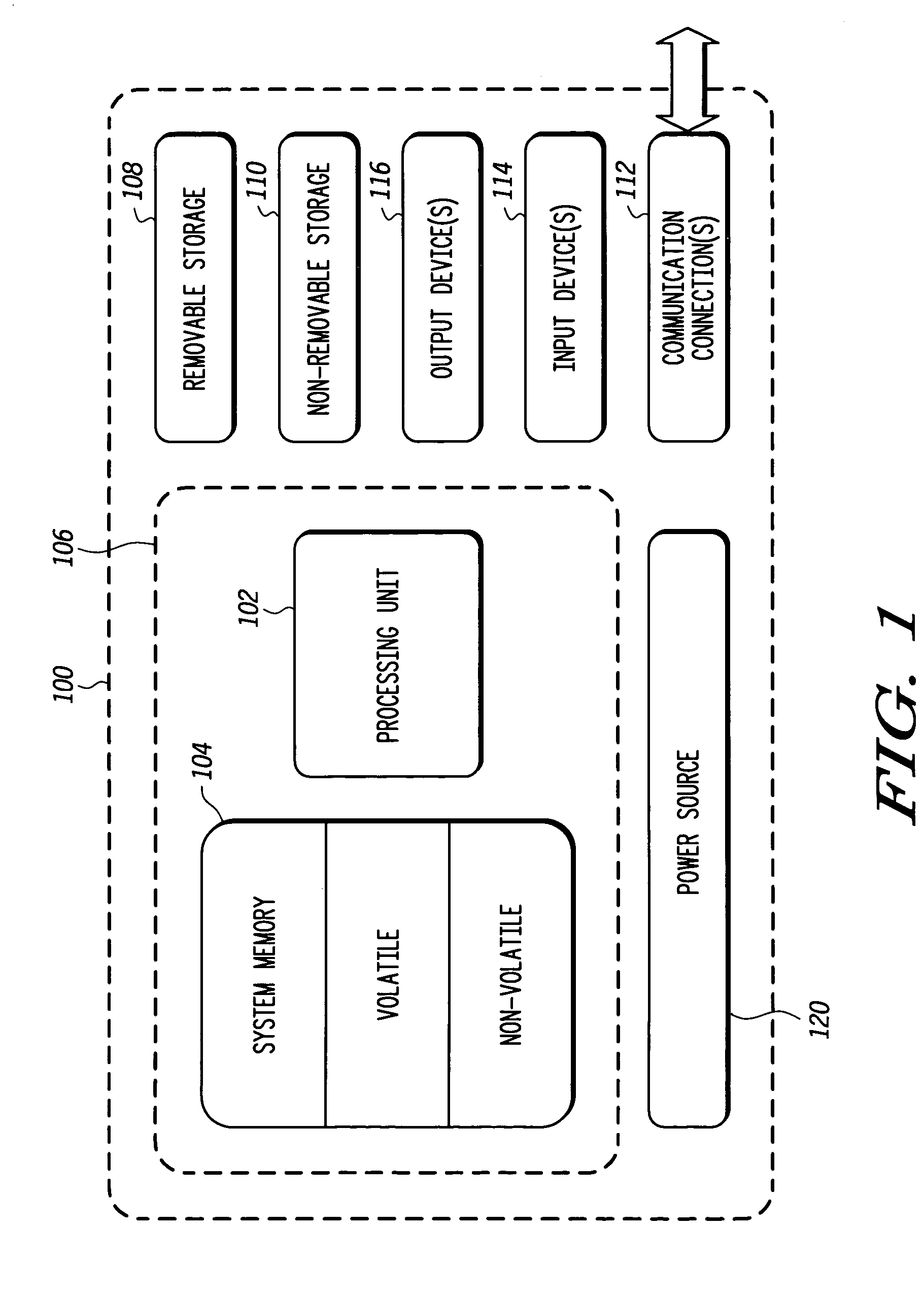
[0019]Turning to the drawings, wherein like reference numerals refer to like elements, the invention is illustrated as being implemented in a suitable computing environment. Although not required, the invention will be described in the general context of computer-executable instructions, such as program modules, being executed by a personal computer. Generally, program modules include routines, programs, objects, components, data structures, etc. that perform particular tasks or implement particular abstract data types. Moreover, those skilled in the art will appreciate that the invention may be practiced with other computer system configurations, including hand-held devices, such as personal digital assistants (PDAs) and cellular phones, multi-processor systems, microprocessor based or ...


PUM


Abstract

A method for removing direct current (DC) interference from a signal received by a communication receiver is provided that removes both a DC offset signal induced by the communication receiver and transmitter. The method includes removing the estimated DC offset from the received signal, correcting a frequency shift in the received signal, estimating a second DC offset signal induced by a source of the received signal, such as a transmitter and removing the estimated second DC offset from the received signal. The receiver DC offset signal is estimated and removed prior to performing a timing carrier offset correction using Barker code manipulation to remove receiver-induced DC offset interference and to sum all Barker chips after effectively multiplying Barker codes to correlate to a Barker sequence unaffected by the receiver DC offset signal.

Description

BACKGROUND OF THE INVENTION[0001]1. Field of the Invention[0002]This invention in general relates to communication devices and in particular to receivers and transmitters subject to DC interference.[0003]2. Description of the Related Art[0004]Wireless communication devices proliferating the market place include newer, smaller, more efficient technologies. Wireless telephones are now capable of performing web-enabled services, and packaging for such telephones continues to decrease in size yet have additional user-appreciated functions.[0005]Consumer grade wireless devices have spurred the development of radio frequency electronics with a renewed emphasis on low cost. One receiver architecture which has seen widespread use in consumer wireless devices is referred to as a direct conversion receiver. Direct conversion receivers are simple and inexpensive but tend to have lower performance than the multiple conversion or super heterodyne architectures used in more expensive receivers. O...

Claims


Application Information

Patent Timeline
Patent Type & Authority Patents(United States)
IPC IPC(8): H04B1/10G06F3/033H04B1/30H04L25/06H04L27/00
CPCH04B1/30H04L25/062H04L25/064H04L2027/0095
Inventor CHEN, WEIZHONGMOLINA, ROBERT
Owner APPLE INC
Why Eureka
Try Eureka