
Resettable latching MEMS shock sensor apparatus and method

a shock sensor and latching technology, applied in the field of low power determination, can solve the problems of large-scale devices, low power and unpowered shock sensors currently exist, and low power methods of determining

Active Publication Date: 2007-09-11
MORGAN RES CORP
View PDF16 Cites 21 Cited by
  • Summary
  • Abstract
  • Description
  • Claims
  • Application Information

AI Technical Summary

Benefits of technology

"The present invention provides a low-power micro-machined shock sensor with adjustable sensitivity and the ability to detect shock levels separate from the latching function. The sensor uses a micromachined proof mass connected to a substrate through flexures, which allows for the detection of shock loads through displacement of the proof mass. The sensor is nearly zero-powered except when providing a trigger signal and can be latched for interrogation at a later date or reset to detect the next event. The invention provides a solution for detecting shock loads with low power consumption and offers flexibility for various applications."

Problems solved by technology

Current battery-powered embedded sensor systems that perform this type of monitoring often require a low power method of determining when a certain level of shock has been reached.
Low power and unpowered shock sensors currently exist.
However, they are large-scale devices such as the catches used in automotive seat belts.
These devices operate in a similar fashion and provide a similar function as the present invention, but are not in a form factor suitable for integration with microdevices, and are not fabricated using techniques that are compatible with microelectronics or micro-electromechanical systems (“MEMS”) devices.
The fundamental problem is that such a system must continuously power the sensor and analog trigger circuitry, creating a constant power draw on the batteries.
Even using the latest in low-power devices and highest capacity batteries, systems that continuously power any sensor will only operate for 5-10 years.
As embedded miniature sensors get smaller, and as batteries are reduced in size and capacity, the use of lower power and unpowered devices will become more critical.

Method used


Image

  • Resettable latching MEMS shock sensor apparatus and method
  • Resettable latching MEMS shock sensor apparatus and method
  • Resettable latching MEMS shock sensor apparatus and method

Examples


Embodiment Construction

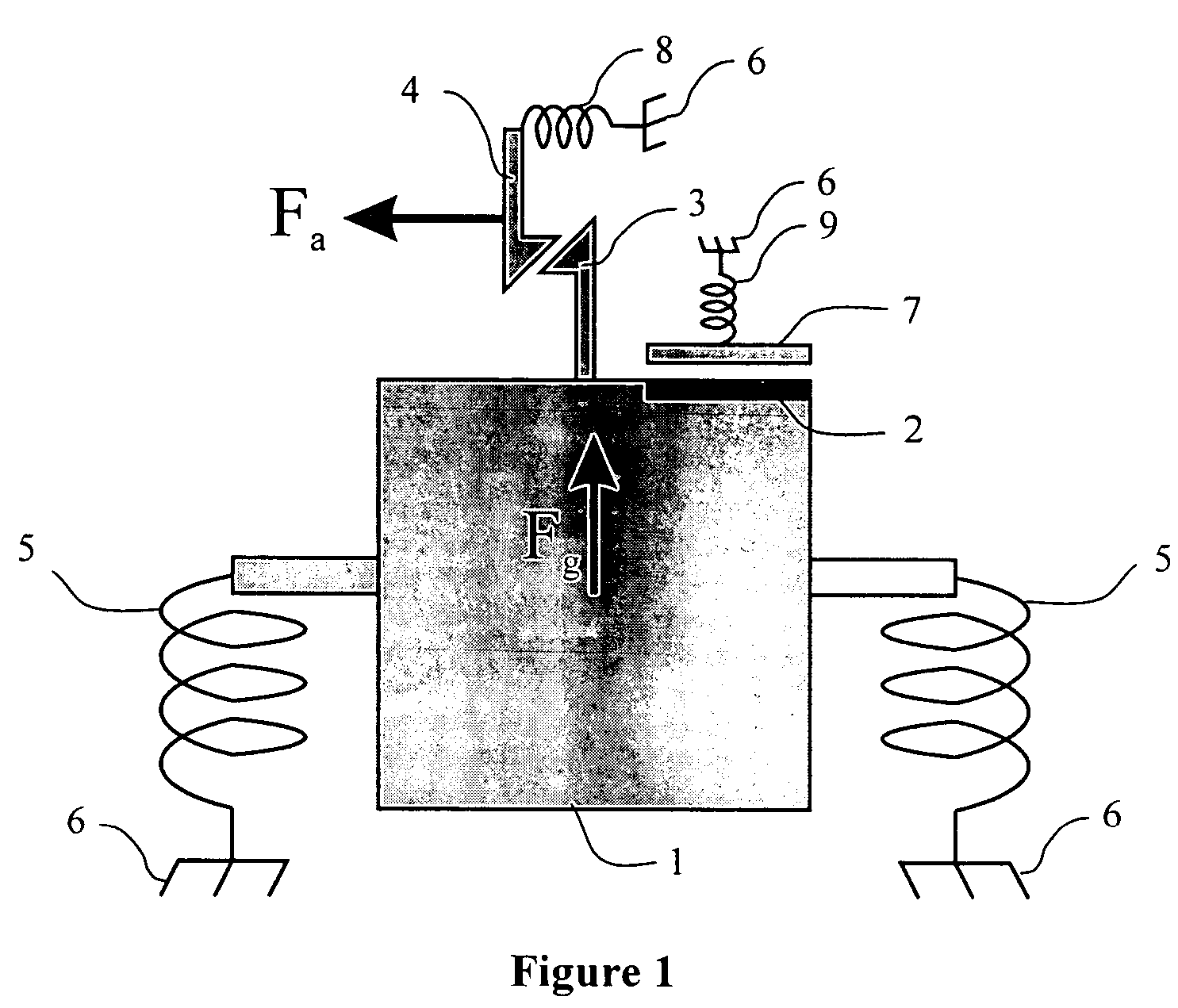
[0029]The illustrated embodiment of the invention is fabricated in a thick layer of silicon or other conductor material that has been released from a rigid substrate. Within this thick layer of material, a proof mass, a set of flexures, multiple contacts, multiple latch and pawl structures, multiple actuators, and multiple anchors and pads are fabricated.

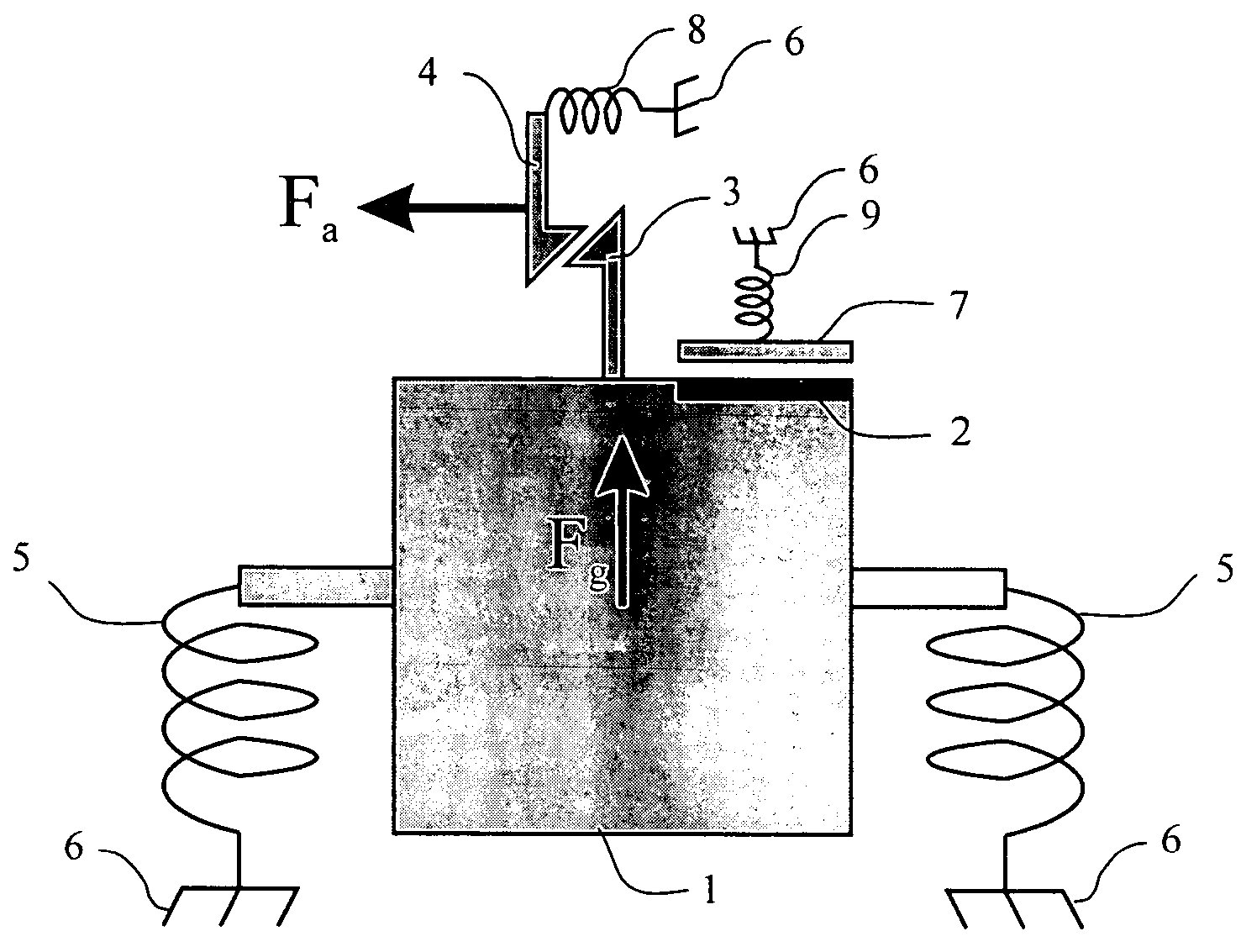
[0030]FIG. 1 illustrates a schematic diagram of one embodiment of the invention. The invention utilizes a micromachined proof mass structure 1 attached to the substrate (not illustrated) via anchors 6 through proof mass flexures 5. The proof mass structure 1 includes a contact area 2 and a latch 3. Under a shock load, the inertia of the proof mass yields a force, Fg, that displaces the mass sufficiently to force the latch 3 to engage with a similar latch on a thin pawl 4 attached to the substrate via anchor 6 through pawl flexure 8. The force also causes the proof mass contact area 2 to connect with the contact 7 that is attached to...


PUM

PropertyMeasurementUnit
latching distanceaaaaaaaaaa
thicknessaaaaaaaaaa
thicknessaaaaaaaaaa

Abstract

The Resettable Latching MEMS Shock Sensor provides the capability of recording external shock extremes without consuming electrical power. The device incorporates a shock sensitive suspended proof mass, spring-loaded contacts, latches, and actuators for device reset. The device can be designed, hardwired, or programmed to trigger at various shock levels. The device can be fabricated in a simple micromachining process that allows its size to be miniaturized for embedded and portable applications. During operation, the device consumes no quiescent power. The device can be configured to close a circuit, switch an interrupt signal, or switch some other electrical trigger signal between devices at the time of a shock extreme being reached, or it can be configured to latch and be polled at some time after the shock limit has occurred.

Description

REFERENCE TO RELATED APPLICATIONS[0001]This application claims priority to Provisional Patent Application U.S. Ser. No. 60 / 619,496, entitled “Resettable Latching MEMS Shock Sensor” and filed on Oct. 15, 2004, which is fully incorporated herein by reference.GOVERNMENT LICENSE RIGHTS[0002]This invention was made with Government support under contract MDA972-03-C-0010, awarded by the Defense Advanced Research Projects Agency (“DARPA”). The Government has certain rights in the invention.BACKGROUND[0003]1. Field of the Invention[0004]The present invention relates generally to a shock sensor and method for monitoring shock. More particularly, the present invention relates to a low-power and unpowered micro-electromechanical shock sensor using a micromechanical suspended proof mass structure.[0005]2. Background of the Invention[0006]Embedding miniature sensors in products, systems, storage and shipping containers, and other items allows the monitoring of those items to determine health, ma...

Claims


Application Information

Patent Timeline
Patent Type & Authority Patents(United States)
IPC IPC(8): G01M7/00G01N3/30G01N3/32G01P15/00
CPCG01P15/0891H01H35/14H01H1/0036H01H35/143H01H2001/0047
Inventor KRANZ, MICHAEL S.JENKINS, ARTHUR A.
Owner MORGAN RES CORP
Learn More