Remote pipeline acoustic inspection

a pipeline and remote inspection technology, applied in the direction of fluid tightness measurement, instrumentation, fluid leakage detection, etc., can solve the problems of loss of production and cost penalties, inability to access the interior of the pipeline, and inability to examine a small section of the pip

Inactive Publication Date: 2007-09-11
UNIV OF MANCHESTER
View PDF10 Cites 75 Cited by
  • Summary
  • Abstract
  • Description
  • Claims
  • Application Information

AI Technical Summary

Benefits of technology

[0008]The apparatus may be used in pipelines which carry all forms of fluid and is therefore applicable to e.g. steam, oil and water, gas pipelines. The apparatus operates remotely and removes the need for local inspection of individual pipes.

Problems solved by technology

In these circumstances, it will not be possible to access the interior of the pipes during plant operation.
This means that visual inspection of the interior of the pipes requires interruption of the plant operation, in most situations leading to a loss of production and cost penalties.
A principal disadvantage of using ultrasound in this way is that only a small section of the pipe can be examined at one time i.e. the inspection is limited to the short length of the pipe at which the ultrasound is directed.
Therefore, the inspection of a long pipe, or worse a pipeline network, will occupy a considerable amount of time since the ultrasound generator and detector must be placed adjacent to each section of the pipe which needs to be examined.
Moreover, there are many situations in which the outer wall of the pipe will not be easily accessible as may occur, for example, if a pipe passes through a radioactive area in a nuclear power station.
Clearly, it would be difficult (or impossible) to use the localised ultrasound method could not be used to inspect these pipes.
The method suffers from the disadvantage that it is not applicable to pipe networks.

Method used


Image

  • Remote pipeline acoustic inspection
  • Remote pipeline acoustic inspection
  • Remote pipeline acoustic inspection

Examples


Embodiment Construction

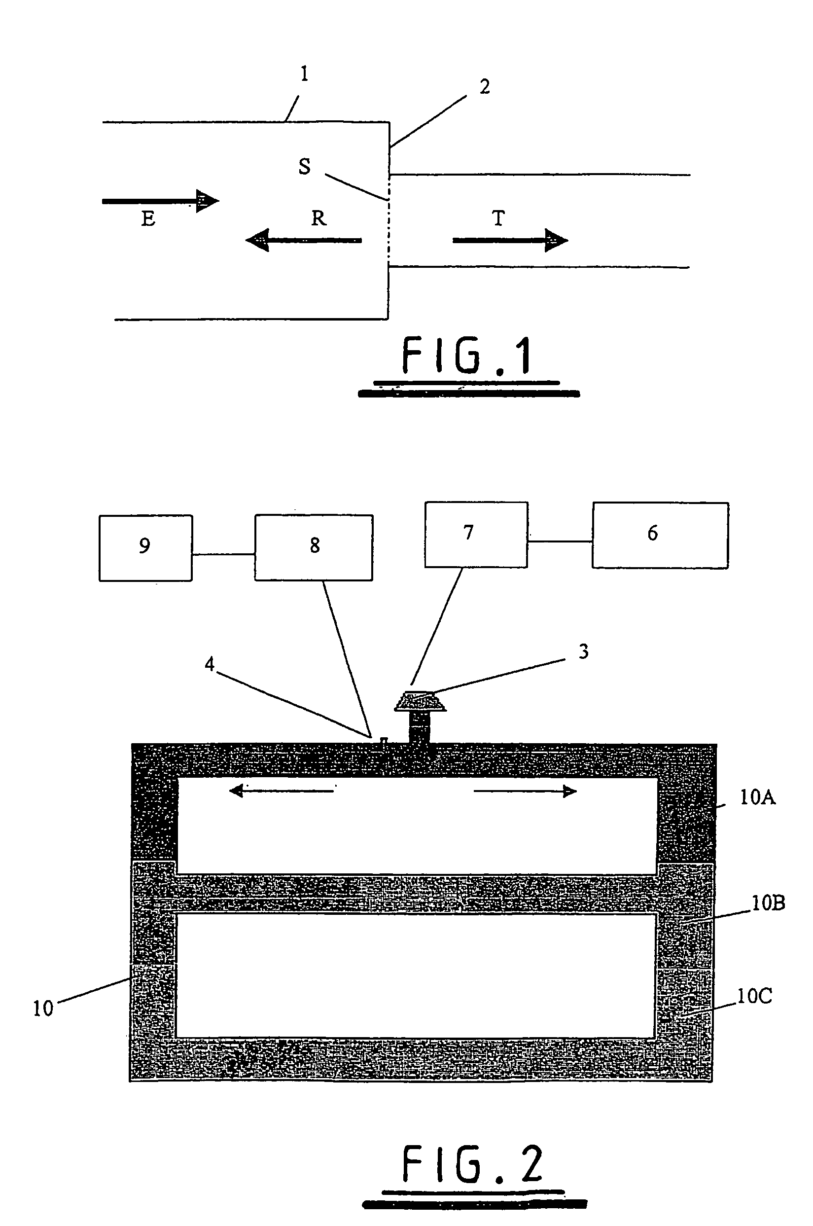
[0038]Referring to FIG. 1, an acoustic signal E propagates along a pipe 1. A change of the diameter of the pipe 1 which might, for example, be caused by a partial blockage of the pipe, is shown schematically at 2. The change of pipe diameter causes a change of the impedance experienced by the acoustic signal E as it propagates along the pipe 1. This change of impedance is most easily represented as a step change, as shown schematically as the dotted line S in FIG. 1. A fraction R of the energy of the incident acoustic signal is reflected back by the step change of acoustic impedance, and the remainder T of the acoustic signal continues to propagate in a forwards direction along the pipe.

[0039]The impedance experienced by an acoustic signal in a pipe is defined as the ratio of the excess wave pressure to the volumetric flow (in the direction of propagation). The reflected signal R, which is dependent on the step change of impedance in the pipe, is determined using the equation:

[0040]...


PUM

PropertyMeasurementUnit
timeaaaaaaaaaa
reflectionaaaaaaaaaa
lengthaaaaaaaaaa

Abstract

A pipe inspection apparatus comprising an acoustic source (3) for location at a first position in a pipe or pipe network, one or more acoustic or pressure detectors (4) for location at one or more positions in the pipe or pipe network, means for recording and/or displaying a signal detected by the one or more detectors following the generation of an acoustic pulse, and means for allowing the comparison of the detected signal with a predetermined reference signal, differences between the detected and reference signals being indicative of a blockage or leakage in the pipe or pipe network (10).

Description

BACKGROUND OF THE INVENTION[0001]The present invention relates to the remote inspection of pipeline systems and particularly, though not exclusively, to a method for the remote detection of pipeline blockages and leakage.[0002]Power plants, chemical processing plants and oil processing plants typically include many pipes, often arranged in complex interconnecting networks. In order to maximise operational efficiency, these plants will often be run without interruption twenty-four hours per day and seven days per week. In these circumstances, it will not be possible to access the interior of the pipes during plant operation. This means that visual inspection of the interior of the pipes requires interruption of the plant operation, in most situations leading to a loss of production and cost penalties.[0003]Several methods have been developed for inspecting the interior of pipes without requiring internal access to the point of inspection. One known method is to direct ultrasound thro...

Claims


Application Information

Patent Timeline
Patent Type & Authority Patents(United States)
IPC IPC(8): G01N29/04G01N29/14G01M3/24
CPCG01M3/243
Inventor SHAMOUT, MOHAMMAD NTURNER, JOHN TLENNOX, BARRYSMITH, DAVID
Owner UNIV OF MANCHESTER
Why Eureka
Try Eureka