Electrical connector with contact

Inactive Publication Date: 2007-09-11
HON HAI PRECISION IND CO LTD
View PDF8 Cites 1 Cited by
  • Summary
  • Abstract
  • Description
  • Claims
  • Application Information

AI Technical Summary

Benefits of technology

[0008]An electrical connector according to an embodiment of the present invention includes an insulative housing adapted to engage a conductive contact. The conductive contact has a tail end, wherein the tail end is angled and has a generally dished shape such that at least a portion of the tail end terminates within a hole, plated with a conductive material, in the contact pad of the circuit board. The dished shape of the conductive contact tail end has th

Problems solved by technology

Since the solder connection alone is not a reliable mechanical means of strength, the SMT technology is limited by the package pin count.
That is because, if the shape of the conductive contact tip is d

Method used


Image

  • Electrical connector with contact
  • Electrical connector with contact
  • Electrical connector with contact

Examples


Embodiment Construction

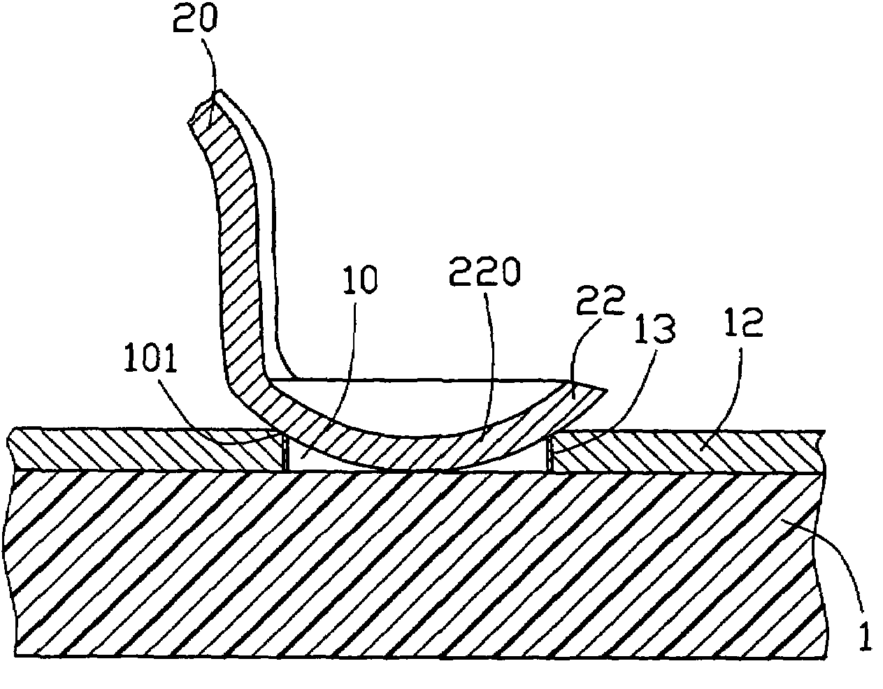
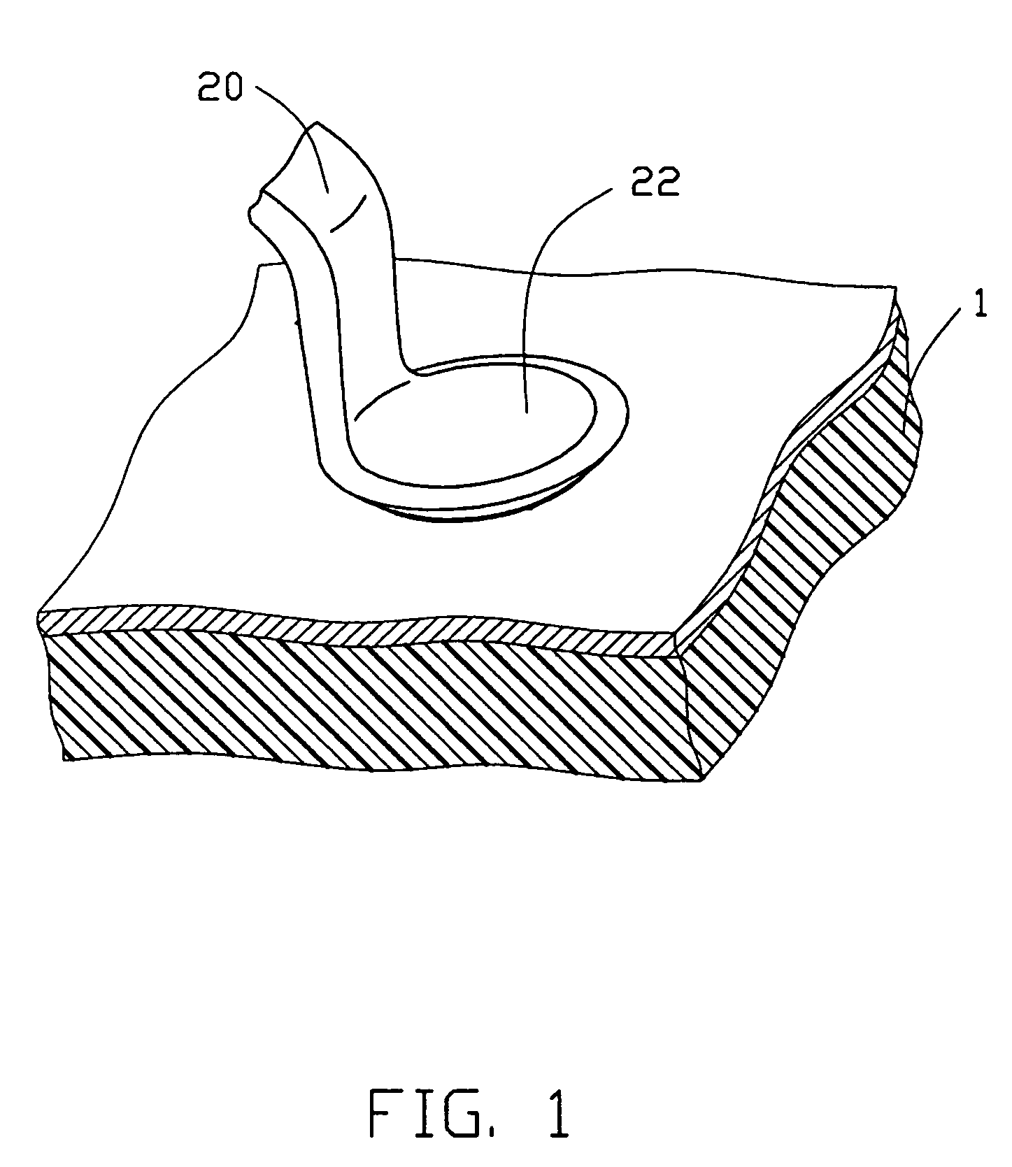
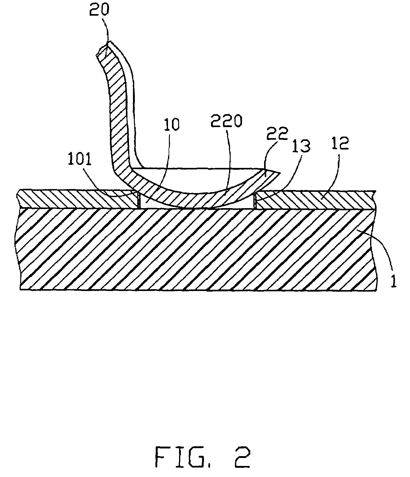
[0013]As known in CMT, an electrical connector is employed to have its conductive contact tips within holes or wells 10 defined in contact pads 12 of the substrate 1 so as to form an electrical connection between the conductive contact tips and the respective contact pad 12 of the substrate 1 through the holes 10. The electrical connector typically includes an insulative housing, 30 preferably in a form of a substantially rectangular box (not shown), adapted to engage conductive contacts 20, arranged in rows and columns. As shown in FIGS. 1 to 3, the conductive contact 20 of this embodiment includes the contact tip or tail end, wherein the tail end includes an angled contact portion 22, the contact portion 22 has a generally dished shape with its outer contact surface 220 convex towards the hole 10 of the substrate 1. More specifically, the tail end of the conductive contact 20 has a substantially semi-spherical outer contact surface 220. However, in other embodiments, the contact p...


PUM


Abstract

An electrical connector includes an insulative housing adapted to engage a conductive contact (20). The conductive contact has a tail end, wherein the tail end (22) is angled and has a generally dished shape such that at least a portion of the tail end terminates within a hole (10) in a contact pad (12) of a circuit board (1). The conductive contact tail end in a dished shape has the advantages of facilitating the guiding of the tail end into or out of the hole of the circuit board during wipe actions, without removing gold plated layer, and of achieving a reliable travel of the tail end across the hole of the contact pad of the circuit board.

Description

BACKGROUND OF THE INVENTION[0001]1. Field of the Invention[0002]The present invention relates to the art of electrical connectors, and more particularly to electrical connection between a conductive contact of an electrical connector and a contact pad of a substrate.[0003]2. The General Background[0004]A microelectronic package typically interconnects with a substrate member, such as a motherboard, a printed circuit board or an interposer, through the use of an electrical connector. A variety of connectors are used in the microprocessor industry, most of which provide a relatively quicker and easy interface between the microelectronic package and the substrate.[0005]Connectors are available with various mounting technologies, including surface mount technology (SMT) and compression mount technology (CMT). SMT socket connectors use standard reflow-soldering methods for mounting to the substrate. With higher pin counts, increased force is needed for the microelectronic package to make...

Claims


Application Information

Patent Timeline
IPC IPC(8): H01R12/00H01R12/57
CPCH05K3/325H05K2201/0969H05K2201/10628H05K2201/10795H05K2203/167
Inventor POLNYI, IGOR
Owner HON HAI PRECISION IND CO LTD
Why Eureka
Try Eureka