Imaging device

Active Publication Date: 2010-08-12
BAE SYSTEMS PLC
View PDF19 Cites 59 Cited by
  • Summary
  • Abstract
  • Description
  • Claims
  • Application Information

AI Technical Summary

Benefits of technology

[0019]Any surface of the faceplate with an angled surface which is not orthogonal to the longitudinal axis of the optical fibers may be modified in or

Problems solved by technology

Modern silicon CCD and CMOS image sensors are becoming extremely small, so that the package size of commercial miniature cameras is becoming dominated by the image forming optics, even if the latter is only a structure supporting a pinhole.
However, such sensor design and manufacture is likely to be costly.
However in order to obtain high deflection efficiencies over a wide field of view it would be necessary to

Method used


Image

  • Imaging device
  • Imaging device
  • Imaging device

Examples


Embodiment Construction

[0046]Exemplary embodiments of the present invention will now be described in more detail, by way of example only, with reference to the accompanying drawings.

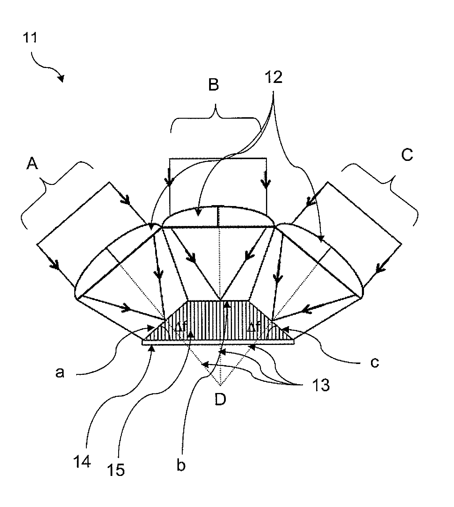
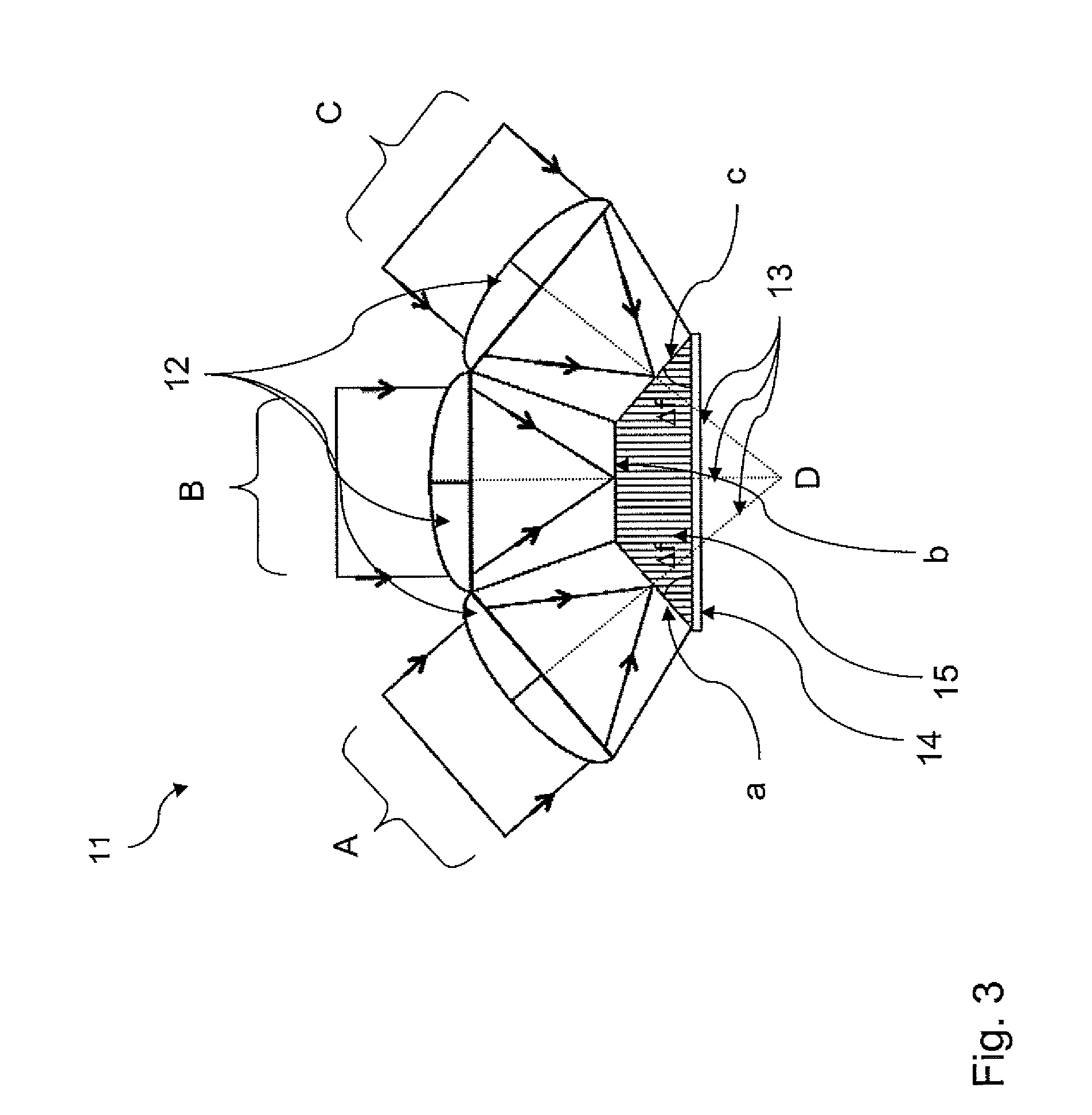
[0047]Referring now to FIG. 3, an imaging device 11 according to one embodiment of the present invention includes a plurality of microlenses 12 arranged such that the axis 13 of each of the microlenses converge at a point D, i.e. the microlenses point in different directions from one another to provide a wide field of view when the images received from the microlenses are combined. The microlenses are coupled to a substantially planar sensor 14 by light guiding arrangement 15 including a plurality of light guides, and which in the exemplary embodiment of the invention are provided by a fiber optic faceplate (FOFP). The fiber optic face plate 15 includes a number of facet surfaces a, b, c. Facet a receives incident light A, facet b receives incident light B and facet c receives incident light C. The fiber optic faceplate 15 has...


PUM


Abstract

An imaging device, particularly but not exclusively for use in a targeting sensor for missile seekers. The imaging device including at least one lens; a substantially planar sensor having a plurality of pixels; a light guiding arrangement for directing light received via said lenses toward said sensor; in which said light guiding arrangement includes a plurality of light guides.

Description

RELATED APPLICATION INFORMATION[0001]This application is a United States National Phase patent application of International Patent Application No. PCT / GB2008 / 050698 which was filed on Aug. 13, 2008, and claims priority to British Patent Application No. 0715998.1, filed on Aug. 16, 2007, and claims priority to European Patent Application No. 07270042.0, filed on Aug. 16, 2007, the disclosures of each of which are incorporated herein by reference.FIELD OF THE INVENTION[0002]This invention relates to an imaging device, particularly but not exclusively to a miniature imaging device for imaging in the near infra-red region of the electromagnetic spectrum.BACKGROUND INFORMATION[0003]Modern silicon CCD and CMOS image sensors are becoming extremely small, so that the package size of commercial miniature cameras is becoming dominated by the image forming optics, even if the latter is only a structure supporting a pinhole. Recently, there have been demonstrations of ultra-flat, extremely ligh...

Claims


Application Information

Patent Timeline
IPC IPC(8): H01L31/0232H01L27/146
CPCG02B6/06G02B13/06G02B13/08G02B27/102H04N5/33G02B27/123H01L27/14625H04N3/1593G02B27/1066H01L27/14605H04N25/41
Inventor LAYCOCK, LESLIE CHARLESHANDEREK, VINCENT ANDREI
Owner BAE SYSTEMS PLC
Why Eureka
Try Eureka