Different materials-laminate metal plate and different materials-laminate core, and method of producing the same

a technology of laminated metal plates and different materials, applied in the direction of magnetic circuits characterised by magnetic materials, magnetic circuits, stator/rotor bodies, etc., can solve the problems of poor workability, hard to be formed, individual metal plates, etc., and achieve the effect of making metals firmer and easy to exer

Inactive Publication Date: 2007-09-11
MITSUI HIGH TEC INC
View PDF6 Cites 4 Cited by
  • Summary
  • Abstract
  • Description
  • Claims
  • Application Information

AI Technical Summary

Benefits of technology

[0046]at the caulking projections of said first material body of the metal plate of laminated heterogeneous materials and the caulking holes of the second material body of the metal plate of the laminated heterogeneous materials,and therefore, the plurality of metal plates of different material qualities can be easily and stably joined.
[0066]According to the above mentioned structure (14), the process of pushing by the caulking punch is exerted in rows exceeding both ends in the length direction of notch, and therefore, the caulking projections are cut down along the rows exceeding both ends thereof in the length direction of the notches, so that the caulking projections can be deeply cut down to obtain the long fitting parts of the caulk, and at the same time, the cut down caulking projection has, on the bottom, linked parts at the left and right sides, and the joint can be made firmer in the metal plate of laminated heterogeneous materials.

Problems solved by technology

For example, an amorphous property has a very superior magnetic characteristic such as high permeability or low iron loss, but this is poor in the workability and hard to be formed.
As mentioned above, individual metal plates have respective characteristics, but also have poor characteristics.
However, in case of producing the laminated iron core of the motor, if the metal plates have thin thickness, a punching process of the iron core pieces increases for providing the laminated core of a desired laminated thickness, so that productivity lowers.
Then, for heightening the punching productivity, it is assumed to carry out punching through the laminated thin metal plates, but, for example, since the amorphous plate is inferior in the workability, if punching through the laminated thin metal plates, cracks or breakages are caused.
On the other hand, the clad steel necessitates heating at high temperatures and fuse-bonding treatment for metal-joining heterogeneous metals, considerable energy and labor are taken for the production, and high cost is invited.
Further, in the embossing process, a caulking strength by the concave and convex parts of the metal plates to be joined is weak, and might probably come off during processing or transportation.
Bonding by an bonding agent might be exfoliated by expansion of an air remaining between the metal plates to be bonded, impurities adhered to the bonded faces, or weak bonding force, and cost is high.
The joining by the rivets has a problem that parts of the rivets exist as the convexes on an opposite side of the jointed face of the metal plate, and if the convexes contact another metal plate, this metal plate takes scratches.

Method used


Image

  • Different materials-laminate metal plate and different materials-laminate core, and method of producing the same
  • Different materials-laminate metal plate and different materials-laminate core, and method of producing the same
  • Different materials-laminate metal plate and different materials-laminate core, and method of producing the same

Examples


first embodiment

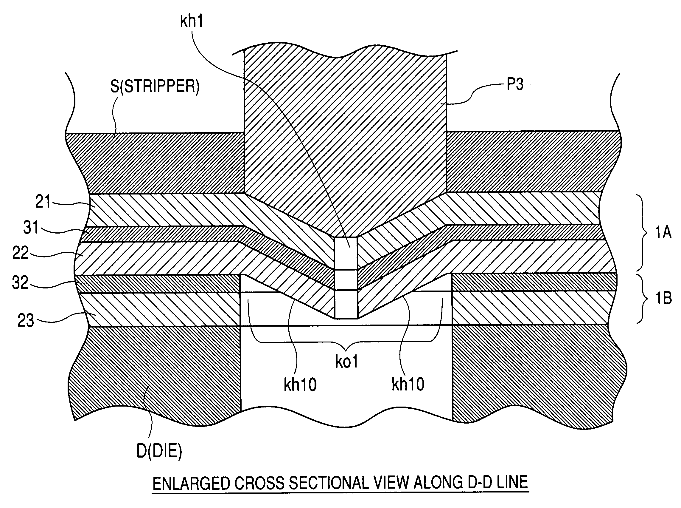
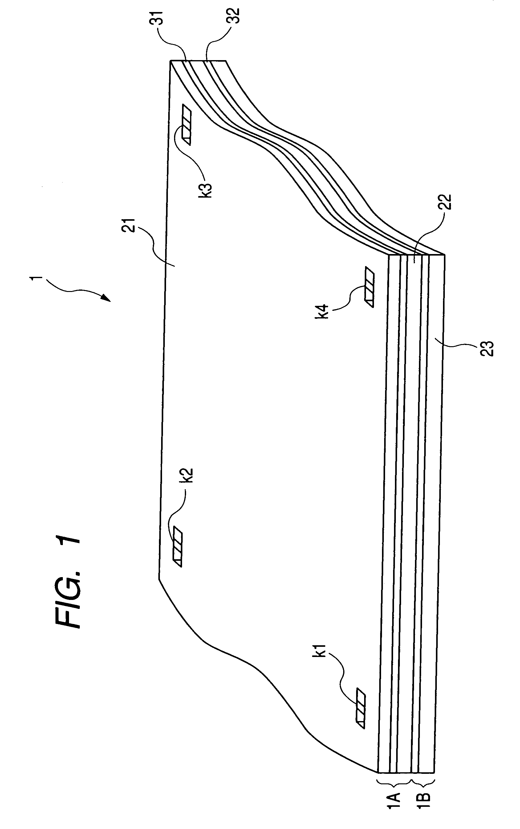
[0103]As shown in FIG. 1, the metal plate 1 of laminated heterogeneous materials as the first embodiment according to the invention is composed by alternately laminating the electromagnetic steel plates (metal plate of the upper side) 21, (metal plates of the lower side) 22, 23, and the amorphous plates of hard workability (metal plates of hard workability) 31, 32, and joining to caulk them at the caulking parts k1, k2, k3, k4.

[0104]The amorphous plates 31, 32 have, other than excellent permeability and holding power, characteristics such as very high electric resistance and very little current loss, that is, least iron loss, but extremely high hardness and hard workability.

[0105]The amorphous plates 31, 32 have ultra thin thickness, for example, as around 0.02 to 0.06 mm.

[0106]The electromagnetic steel plates 21, 22, 23 have the better workability than that of the amorphous plates 31, 32, and also the desirable magnetic characteristic, though being not as the amorphous plates 31, 3...

second embodiment

[0134]Next, explanation will be made to a

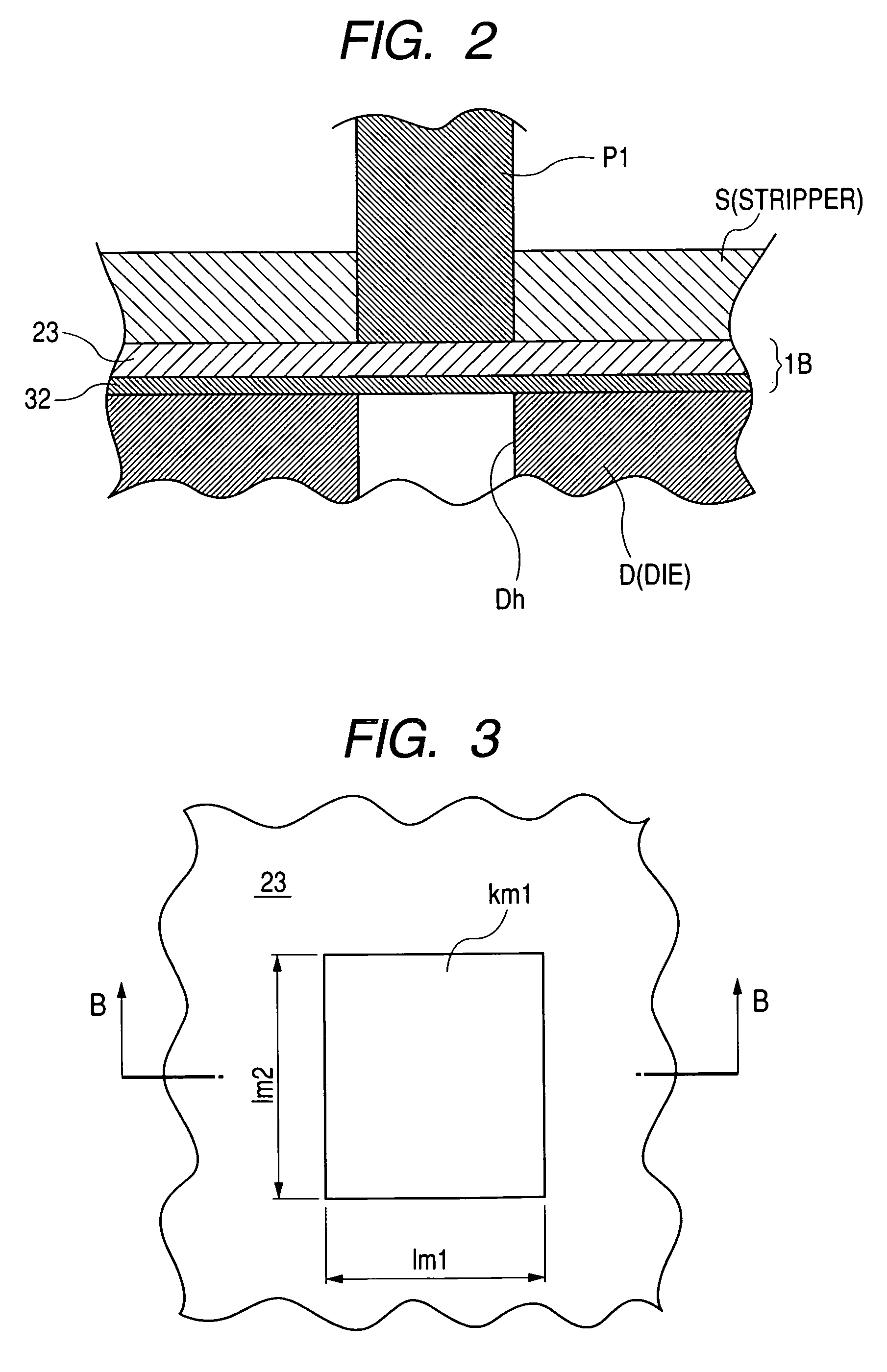
[0135]The metal plate 21 of laminated heterogeneous materials as the second embodiment according to the invention is, as shown in FIG. 10, composed by alternately laminating the electromagnetic steel plates (metal plate of the upper side) 221, (metal plates of the lower side) 222, 223, and the amorphous plates of hard workability (metal plates of hard workability) 231, 232, and joining to caulk them at the caulking parts k21, k22, k23, k24.

[0136]The above structured metal plate 21 of laminated heterogeneous materials is made by the following method.

[0137]Reference will be made to forming of the caulking part k1 and the caulking joint in the metal plate 21 of laminated heterogeneous materials, differently from the above mentioned first embodiment.

[0138]As shown in FIG. 11, a punch P21 is reciprocally moved toward a die hole Dh with respect to the lower layer of the metal plate of laminated heterogeneous materials (second body of the metal plat...

third embodiment

[0159]FIG. 19 is a perspective view of applying the metal plate of laminated heterogeneous materials as the third embodiment according to the invention to the iron core of rotor of motor.

[0160]FIG. 20 is a view of explaining the press processing procedure of making the rotor iron core of motor depending on the metal plate of laminated heterogeneous materials shown in FIG. 19.

[0161]As shown in FIGS. 19 and 23, the iron core 110 of laminated heterogeneous materials as the third embodiment according to the invention is caulked and laminated with the iron core pieces 123 to 126 of a first step (lowest layer) to a fourth step in such manners of holding the amorphous iron core pieces 111, 112, 113, 114 between the lower sides and upper sides of the iron core pieces of the electromagnetic steel plates 115-116, 117-118, 119-120, and 121-122, and is applied as the iron core of laminated rotors.

[0162]As shown in FIG. 19, in adjacency of the inside of the iron core 110 of laminated heterogeneo...


PUM

PropertyMeasurementUnit
thicknessaaaaaaaaaa
thicknessaaaaaaaaaa
widthaaaaaaaaaa

Abstract

The invention is to provide a metal plate of laminated heterogeneous materials, and an iron core of the same, where a plurality of metal plates of different material qualities are easily and stably joined, have characteristics over many applications, may attain low production cost, and provide a making method thereof. That is, a metal plate of laminated heterogeneous materials, which is joined by laminating a plurality of metal plates of different material qualities, is joined by caulking a first material body of the metal plate of the laminated heterogeneous materials having notches at intermediate parts thereof, as well as caulking projections formed by cutting down rows of both ends thereof in the length direction of the notches, and a second material body of the metal plate of the laminated heterogeneous materials formed with caulking holes for inserting the caulking projections, at the caulking projections of said first material body and the caulking holes of the second material body.

Description

TECHNICAL FIELD[0001]The present invention relates to a metal plate of laminated heterogeneous materials and a core of laminated heterogeneous materials, which are composed by laminating and joining a plurality of metal plates of different material qualities one another, and a making method thereof.BACKGROUND ART[0002]When making iron cores, or transformers of rotors equipped in motors, those have conventionally been pursued to have preferable magnetic characteristics such as high permeability or small holding power, and less iron loss.[0003]Therefore, for avoiding generation of Joule heat caused by eddy currents as a main cause of the iron loss and generation of magnetic force in a counteracting direction, aiming at interception of the eddy current flow, it is considered to reduce in thickness an electromagnetic steel plate having good magnetic characteristic, and laminate plural sheets of thinned steel plates for producing iron cores or transformers of rotors.[0004]In the above me...

Claims


Application Information

Patent Timeline
Patent Type & Authority Patents(United States)
IPC IPC(8): H02K1/06B32B15/01H02K1/02H02K15/02
CPCB32B15/01H02K15/02H02K1/02Y10T29/49009
Inventor MITSUI, YOSHIAKI
Owner MITSUI HIGH TEC INC
Why Eureka
Try Eureka