Compound heat sink

a heat sink and compound technology, applied in the field of compound heat sinks, can solve the problems of weak graphite sheets, inferior thermal conductivity of z-axis, and large heat generation of electronic devices, and achieve the effect of improving bonding strength and stability, and superior thermal conductivity

Inactive Publication Date: 2014-12-04
HUGETEMP ENERGY
View PDF3 Cites 4 Cited by
  • Summary
  • Abstract
  • Description
  • Claims
  • Application Information

AI Technical Summary

Benefits of technology

[0006]An objective of the present invention is to provide a compound heat sink with superior thermal conductivity in the X-, Y-, and Z-axis, which bonds a first embedding structure of the first layer and a second embedding structure of the second layer for improving the bonding strength and stability between two heterogeneous materials.
[0008]Still another objective of the present invention is to provide a lightweight and thin compound heat sink.

Problems solved by technology

Nonetheless, because electronic devices generate a great deal of heat during operation. how to enable electronic products have excellent heat dissipating efficiency given limited device volume for guaranteeing normal operation of the electronic products and thus extending their lifetime has become the primary challenge for modern electronic products.
Nevertheless, graphite sheets are weak and their thermal conductivity is inferior in the Z-axis.
These problems limit the application of graphite sheets in heat dissipation.
However, under such a bonding method, the existence of the glue layer introduces substantial thermal resistivity between the graphite sheet and the metal sheet, leading to unpromising performance of the compound heat dissipating material in thermal conduction.

Method used


Image

  • Compound heat sink
  • Compound heat sink
  • Compound heat sink

Examples


Embodiment Construction

[0027]In order to make the structure and characteristics as well as the effectiveness of the present invention to be further understood and recognized, the detailed description of the present invention is provided as follows along with embodiments and accompanying figures.

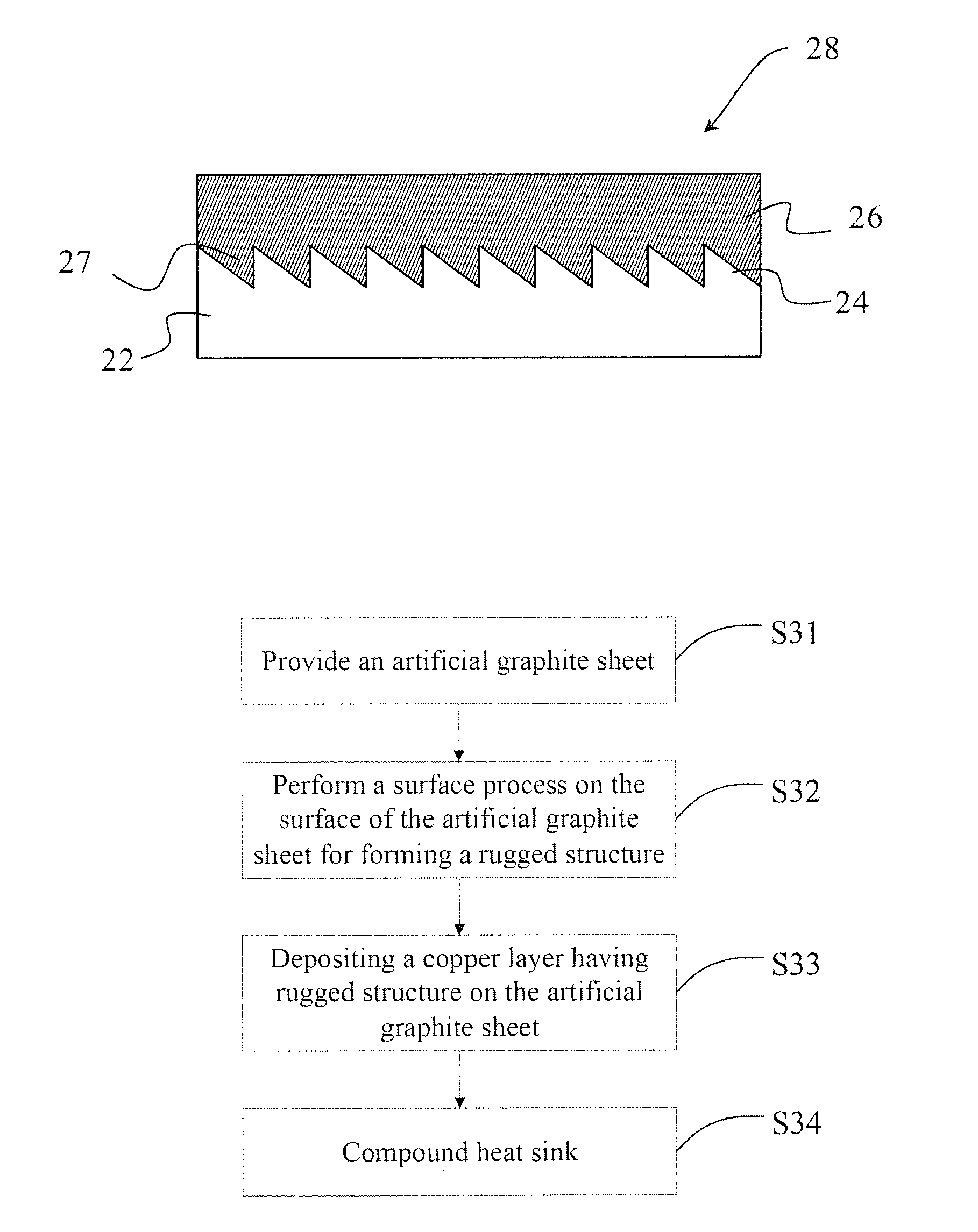
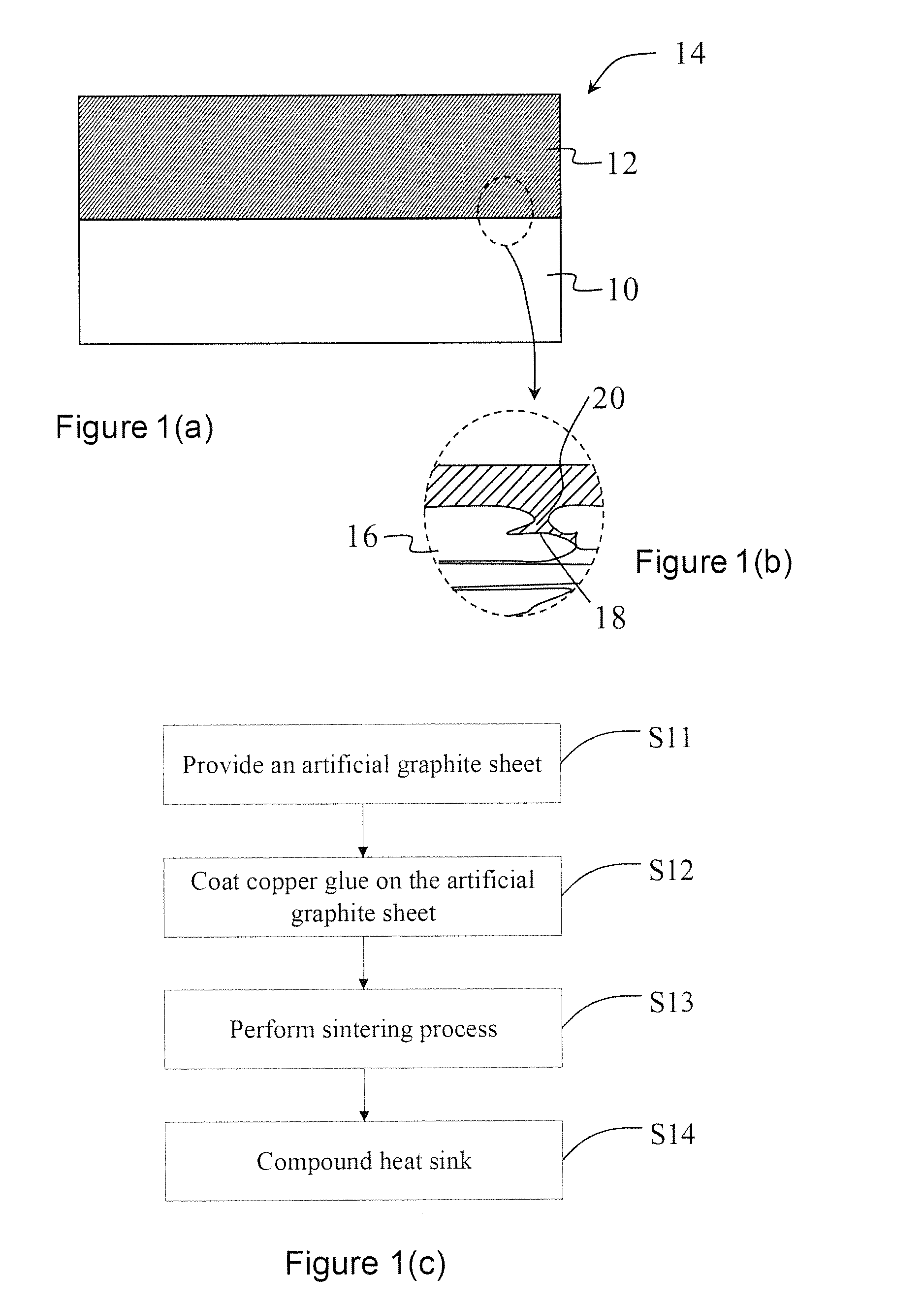
[0028]The spirit of the present invention is to provide a compound heat sink with superior thermal conductivity in the X-, Y-, and Z-axis. The compound heat sink comprises a graphite layer, a metal layer, and a bonding structure located between the graphite layer and the metal layer. The bonding structure can reinforce the bonding strength of the graphite layer and the metal layer.

[0029]According to an embodiment, the bonding structure includes a first embedding structure on a surface of the graphite layer and a second embedding structure on a surface and corresponding to the first embedding structure.

[0030]The first embedding structure described above can be the material of the graphite layer or formed by surface ...


PUM

PropertyMeasurementUnit
thermal conductivityaaaaaaaaaa
areaaaaaaaaaaa
embedding structureaaaaaaaaaa

Abstract

The present invention provides a compound heat sink, mainly comprising a graphite layer and a metal layer. The graphite layer has a first embedding structure on a surface; the metal layer has a second embedding structure on a surface and corresponding to the first embedding structure. The graphite layer and the metal layer are bonded by the first and second embedding structures for increasing the bonding strength between two heterogeneous materials as well as reducing the interfacial heat resistance. Thereby, the stability of heat dissipation performance can be improved.

Description

FIELD OF THE INVENTION[0001]The present invention relates generally to a compound heat sink, and particularly to a compound heat sink having excellent thermal conduction property in all of the X-, Y-, and Z-axis.BACKGROUND OF THE INVENTION[0002]Owing to the developments in technologies and the trend of demands in the consumer market, electronic produces have been developing in the direction of high performance, high speed, and compact size, and hence increasing the relative density of electronic devices. Nonetheless, because electronic devices generate a great deal of heat during operation. how to enable electronic products have excellent heat dissipating efficiency given limited device volume for guaranteeing normal operation of the electronic products and thus extending their lifetime has become the primary challenge for modern electronic products.[0003]Because metal sheets have excellent thermal conduction property in all of the X-, Y-, and Z-axis, metals having high thermal cond...

Claims


Application Information

Patent Timeline
Patent Type & Authority Applications(United States)
IPC IPC(8): F28F3/00B32B15/04
CPCB32B15/04F28F3/00B32B9/041B32B15/18B32B15/20B32B2457/00Y10T428/24545Y10T428/2495Y10T428/31678
Inventor LI, HUNG-YUANCHIANG, TSUNG-CHEN
Owner HUGETEMP ENERGY
Why Eureka
Try Eureka