Method for manufacturing compound heat sink

a heat sink and heat sink technology, applied in the direction of lighting and heating apparatus, modification of conduction heat transfer, paper/cardboard containers, etc., can solve the problems of weak graphite sheets, inferior thermal conductivity of z-axis, and large heat generated by electronic devices, so as to improve bonding strength and stability, the effect of superior thermal conductivity

Inactive Publication Date: 2015-05-21
HUGETEMP ENERGY
View PDF6 Cites 5 Cited by
  • Summary
  • Abstract
  • Description
  • Claims
  • Application Information

AI Technical Summary

Benefits of technology

[0007]An objective of the present invention is to provide a method for manufacturing a compound heat sink, which provides that the compound heat sink has superior thermal conductivity in the X-axis, Y-axis, and Z-axis, which bonds a first embedding structure of the first layer and a second embedding structure of the second layer for improving the bonding strength and stability between two heterogeneous materials.
[0009]Still another objective of the present invention is to provide a lightweight and thin compound heat sink.

Problems solved by technology

Nonetheless, because electronic devices generate a great deal of heat during operation, how to enable electronic products have excellent heat dissipating efficiency given limited device volume for guaranteeing normal operation of the electronic products and thus extending their lifetime has become the primary challenge for modern electronic products.
Nevertheless, graphite sheets are weak and their thermal conductivity is inferior in the Z-axis.
These problems limit the application of graphite sheets in heat dissipation.
However, under such a bonding method, the existence of the glue layer introduces substantial thermal resistivity between the graphite sheet and the metal sheet, leading to unpromising performance of the compound heat dissipating material in thermal conduction.

Method used


Image

  • Method for manufacturing compound heat sink
  • Method for manufacturing compound heat sink
  • Method for manufacturing compound heat sink

Examples


Embodiment Construction

[0030]In order to make the structure and characteristics as well as the effectiveness of the present invention to be further understood and recognized, the detailed description of the present invention is provided as follows along with embodiments and accompanying figures.

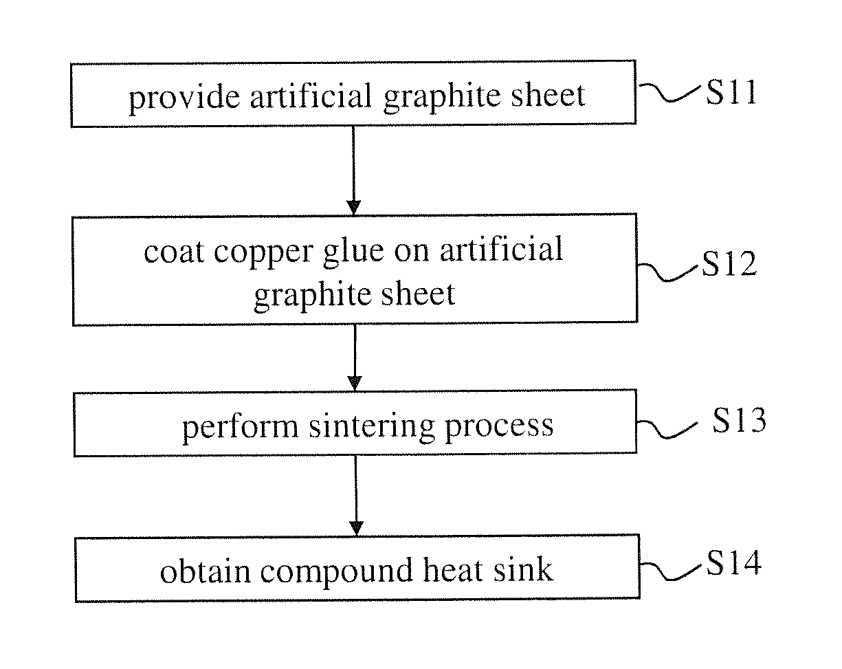
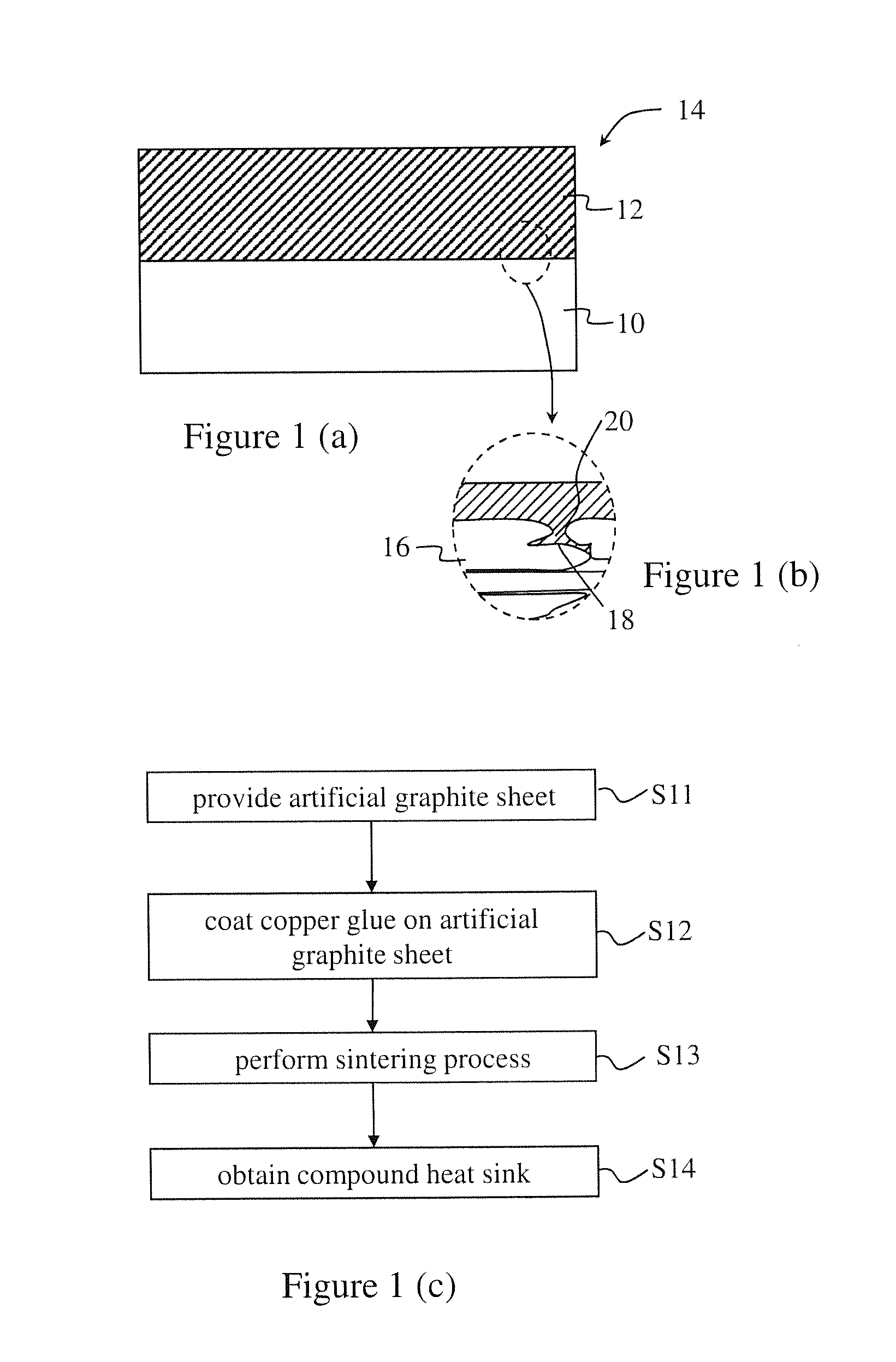
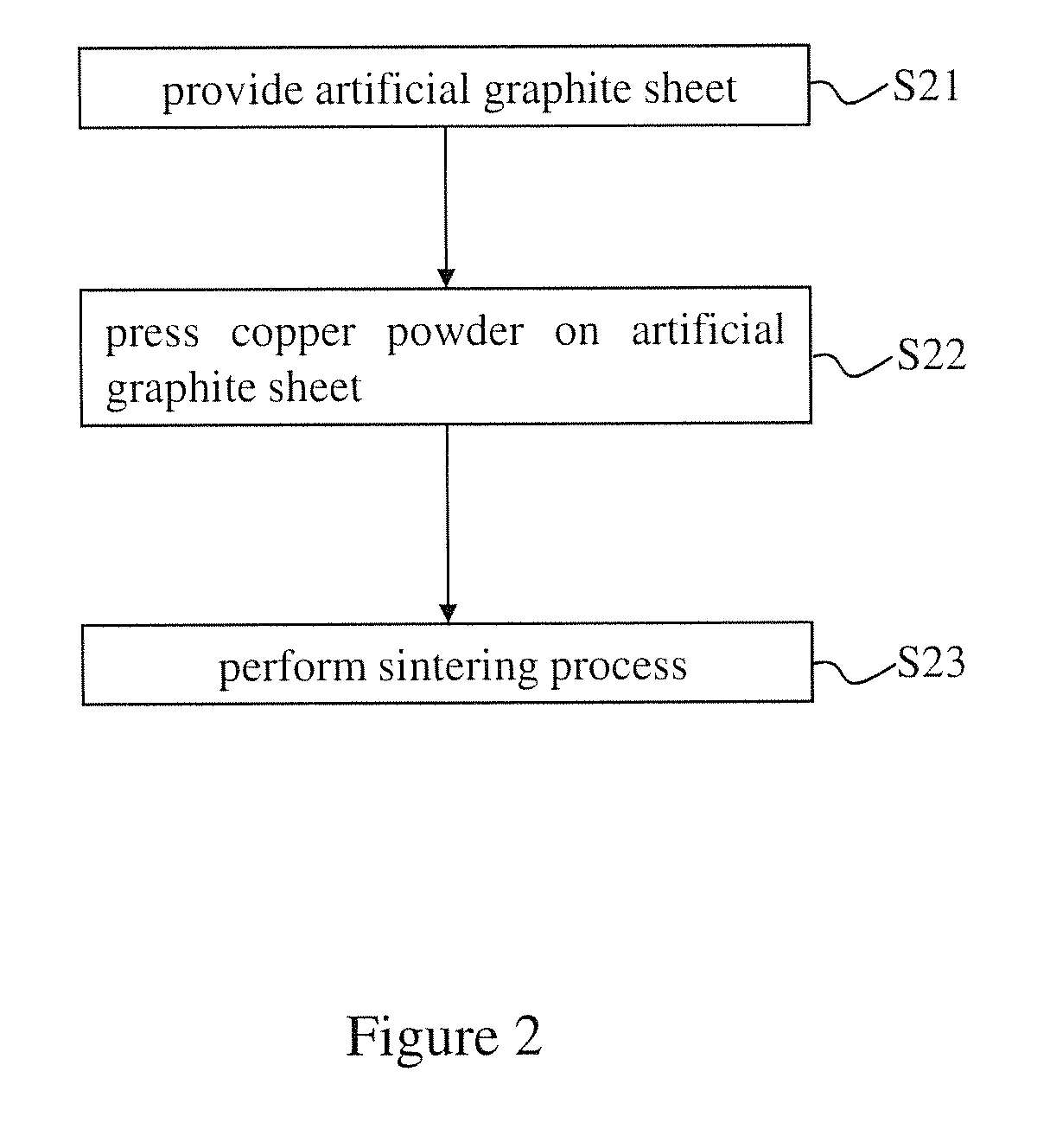
[0031]The spirit of the present invention is to provide a compound heat sink with superior thermal conductivity in the X-axis and Y-axis. The compound heat sink comprises a graphite layer, a metal layer, and a bonding structure located between the graphite layer and the metal layer. The bonding structure can reinforce the bonding strength of the graphite layer and the metal layer.

[0032]The compound heat sink can slow down the increment of temperature of electronic product by fitting higher volumetric heat capacity of metal and higher thermal conductivity of graphite. Thereby, heat dissipation effect will be improved and the increment of the temperature will be slowed down. Although the heat capacity of graphite is ...


PUM

PropertyMeasurementUnit
volumetric heat capacityaaaaaaaaaa
areaaaaaaaaaaa
thicknessaaaaaaaaaa

Abstract

The present invention provides a method for manufacturing a compound heat sink. Firstly, providing an artificial graphite sheet, and then performing a surface treatment process on the artificial graphite sheet to form a rugged structure on the artificial graphite sheet as a first embedding structure. Finally, forming a metal layer covering the rugged structure, and performing a pressing bonding process to form a second embedding structure corresponding to the first embedding structure to bond the metal layer and the artificial graphite sheet. Namely, the artificial graphite sheet and the metal layer are bonded by the first and second embedding structures for increasing the bonding strength between two heterogeneous materials as well as reducing the interfacial heat resistance. Thereby, the stability of heat dissipation performance can be improved, and a volumetric heat capacity of the compound heat sink from 1.1 to 3.5 J / (cm3·K) is provided.

Description

REFERENCE TO RELATED APPLICATION[0001]This Application is being filed as a Continuation-in-Part Application of application Ser. No. 14 / 047,145, filed 7 Oct. 2013, currently pending.FIELD OF THE INVENTION[0002]The present invention relates generally to a method for manufacturing a heat sink, and particularly to a method for manufacturing a compound heat sink having excellent thermal conduction property in all of the X-axis, Y-axis, and Z-axis.BACKGROUND OF THE INVENTION[0003]Owing to the developments in technologies and the trend of demands in the consumer market, electronic produces have been developing in the direction of high performance, high speed, and compact size. and hence increasing the relative density of electronic devices. Nonetheless, because electronic devices generate a great deal of heat during operation, how to enable electronic products have excellent heat dissipating efficiency given limited device volume for guaranteeing normal operation of the electronic products...

Claims


Application Information

Patent Timeline
Patent Type & Authority Applications(United States)
IPC IPC(8): H05K7/20B05D3/12C25D5/34B05D7/00F28F21/02F28F21/08B05D1/36B05D3/02
CPCH05K7/20509B05D1/36B05D3/12C25D5/34B05D7/542F28F21/02F28F21/089B05D3/0254B32B9/041B32B15/18B32B15/20B32B2457/00Y10T428/24545Y10T428/2495Y10T428/31678H01L23/3735H01L23/373H01L23/3736H01L2924/0002Y10T156/10H01L2924/00
Inventor LI, HUNG-YUANCHIANG, TSUNG-CHEN
Owner HUGETEMP ENERGY
Why Eureka
Try Eureka