Electric machine and method of operating the electric machine

a technology of electric machines and electric motors, applied in the direction of electronic commutators, dynamo-electric converter control, motor/generator/converter stoppers, etc., can solve the problems of high replacement costs of these components, and achieve the effect of simplifying installation and efficient operation of electric machines

Inactive Publication Date: 2007-09-11
REGAL BELOIT AMERICA
View PDF45 Cites 52 Cited by
  • Summary
  • Abstract
  • Description
  • Claims
  • Application Information

AI Technical Summary

Problems solved by technology

Replacing these components can be costly.

Method used


Image

  • Electric machine and method of operating the electric machine
  • Electric machine and method of operating the electric machine
  • Electric machine and method of operating the electric machine

Examples


Embodiment Construction

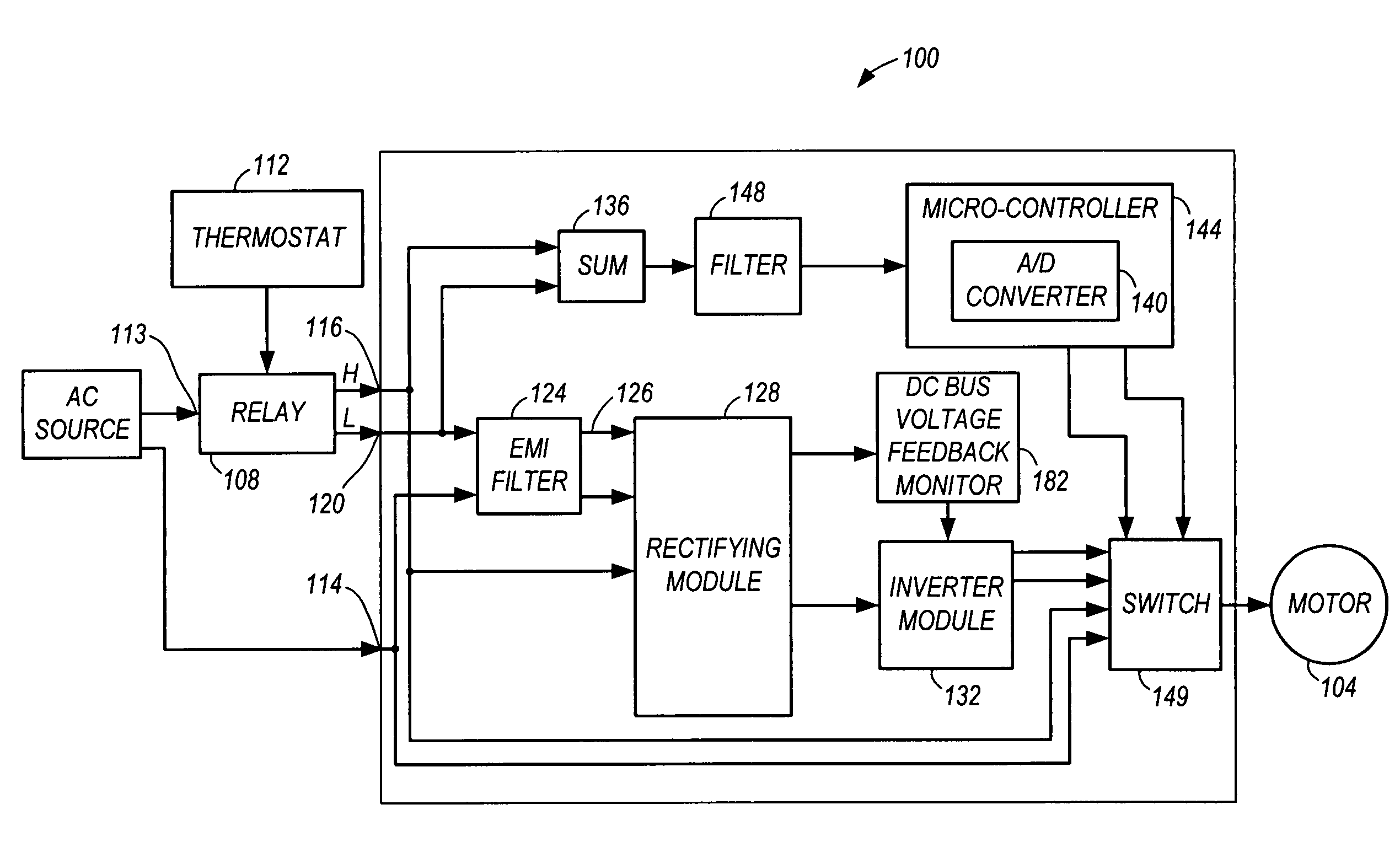
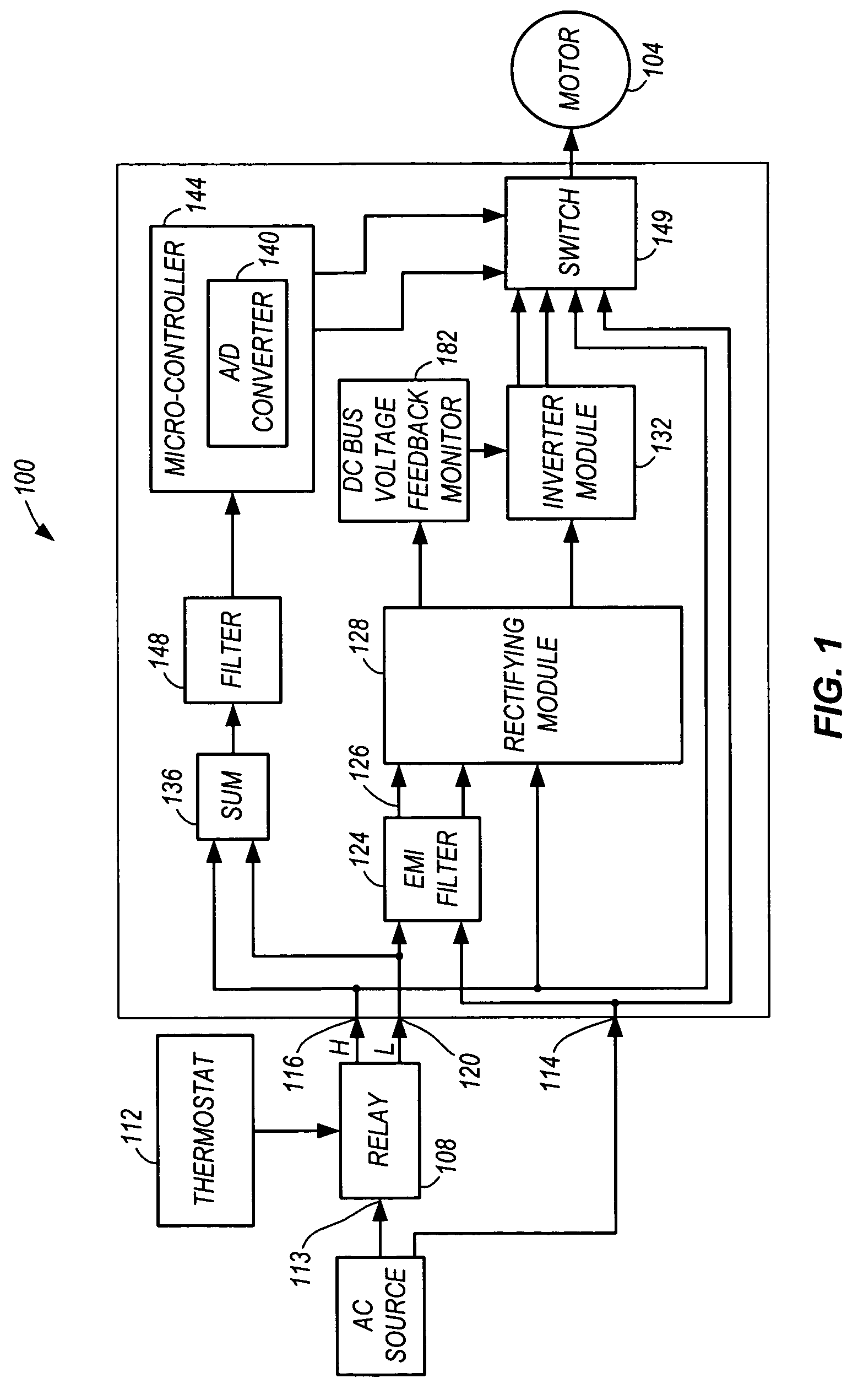
[0022]FIG. 1 shows a block diagram of a FSD interface 100 coupled to an induction motor 104. The interface 100 includes a thermostat relay or tapped winding relay 108 that receives a selection input from a thermostat 112, and power from an alternating current (“AC”) power source line-in 113. The interface 100 also receives a second AC power source line-in at input 114. The tapped winding relay 108 has two speed outputs 116, 120 representing a high-speed signal and a low-speed signal, respectively. More specifically, the tapped winding relay 108 will generate a high-speed signal when the motor 104 is run at a full-speed mode, whereas the tapped winding relay 108 will generate a low-speed signal when the motor 104 is run at a low-speed mode. The low-speed signal output 120 is fed into an electromagnetic interference (“EMI”) filter 124 to attenuate electromagnetic interference to generate a filtered low-speed output 126. The filtered low-speed output 126 and the high-speed signal outpu...


PUM


Abstract

A method of and apparatus for controlling an electric machine. The method can include using a controller to detect whether power is present at a first node of the controller, detect whether power is present at a second node of the controller, generate at least one signal based at least in part on the detection, and energize the electric machine using a detected power when the at least one signal indicates power is present at at least one of the first node, the second node, and a combination of the first node and the second node.

Description

RELATED APPLICATIONS[0001]This patent application is a continuation-in-part of U.S. patent application Ser. No. 10 / 662,052, filed on Sep. 12, 2003, now U.S. Pat. No. 7,102,324; and claims the benefit of U.S. Patent Application No. 60 / 538,717, filed on Jan. 23, 2004, both of which are incorporated herein by reference.BACKGROUND OF THE INVENTION[0002]The invention generally relates to electric machines (e.g., an induction motor), and more particularly to methods of and apparatus for controlling electric machines.[0003]Many methods and apparatuses are used to control an induction motor. Exemplary methods and apparatuses include speed tap changing, triac controls, and fixed speed drive. In changing the speed taps, an effective reduction in voltage or flux is provided to cause the motor to run at a reduced speed by the nature of a slip. The slip is a measurement of how much the movement of the rotor follows the excitation field, and is defined as the difference between the frequency of t...

Claims


Application Information

Patent Timeline
Patent Type & Authority Patents(United States)
IPC IPC(8): H02K21/00H02P1/18H02P27/04
CPCH02P1/18H02P27/04H02P2207/01
Inventor PANT, ALBERT KEITHBRANECKY, BRIAN THOMASMEHLHORN, WILLIAM L.PHILLIPS, ANDREW W.
Owner REGAL BELOIT AMERICA
Why Eureka
Try Eureka