Solid catadioptric lens with two viewpoints

a catadioptric lens and solid technology, applied in the field of optics, can solve the problems of limited use of optical ranging, complex and expensive wide-angle lenses and optical systems, and high cos

Active Publication Date: 2007-09-11
ELECTRONICS SCRIPTING PRODS
View PDF38 Cites 132 Cited by
  • Summary
  • Abstract
  • Description
  • Claims
  • Application Information

AI Technical Summary

Problems solved by technology

Unfortunately, many wide-angle lenses and optical systems are complex and expensive.
It is not evident, however, that this system would be useful in certain machine vision applications since the design does not produce the important feature of a single view-point (SVP).
This system would be useful for many machine vision applications, but would be limited in its use for optical ranging applications involving absolute measurement of distances unless two or more such lenses are used in stereo-vision or multiple-view systems that are well known in the art.

Method used


Image

  • Solid catadioptric lens with two viewpoints
  • Solid catadioptric lens with two viewpoints
  • Solid catadioptric lens with two viewpoints

Examples


Embodiment Construction

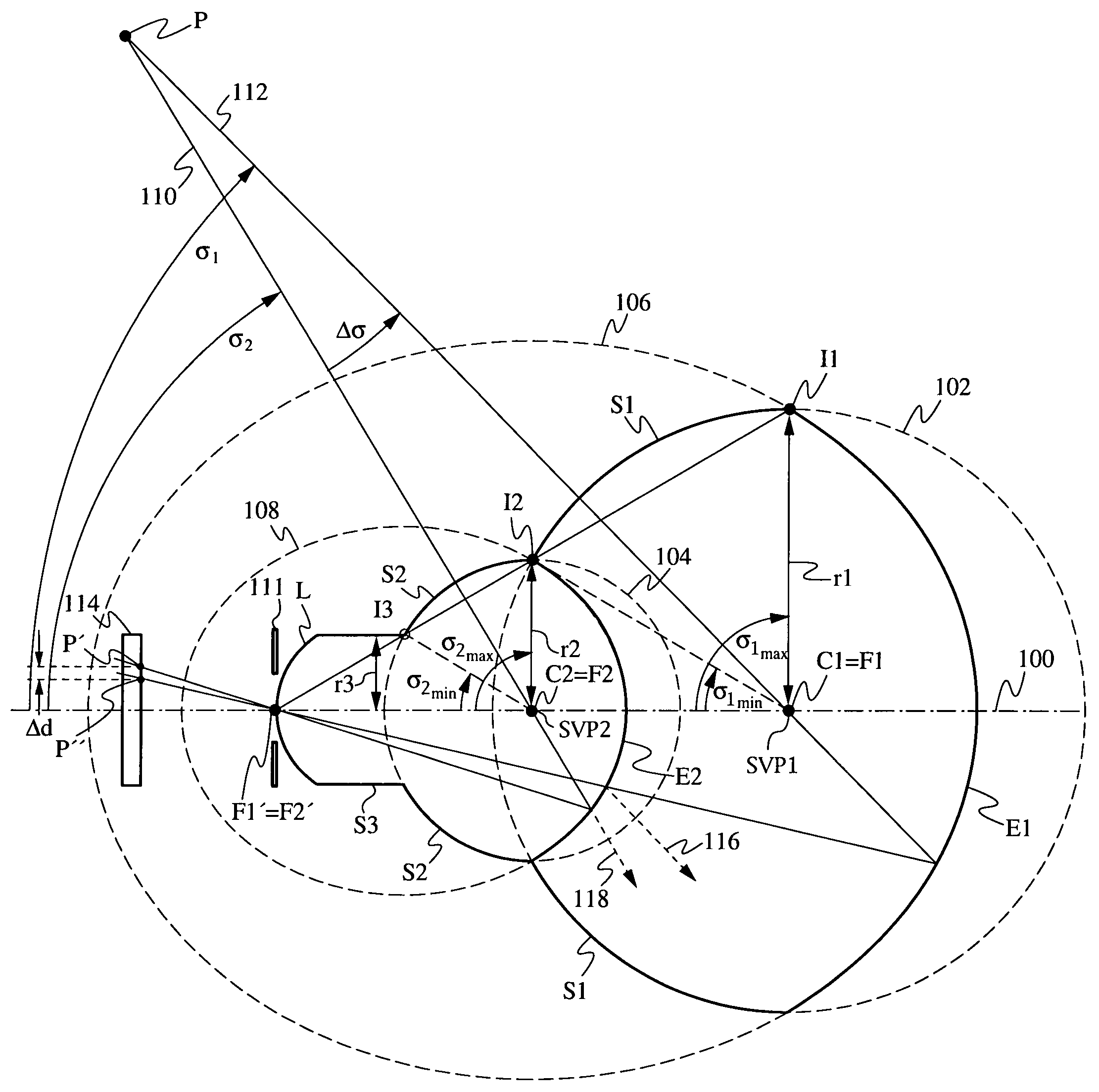
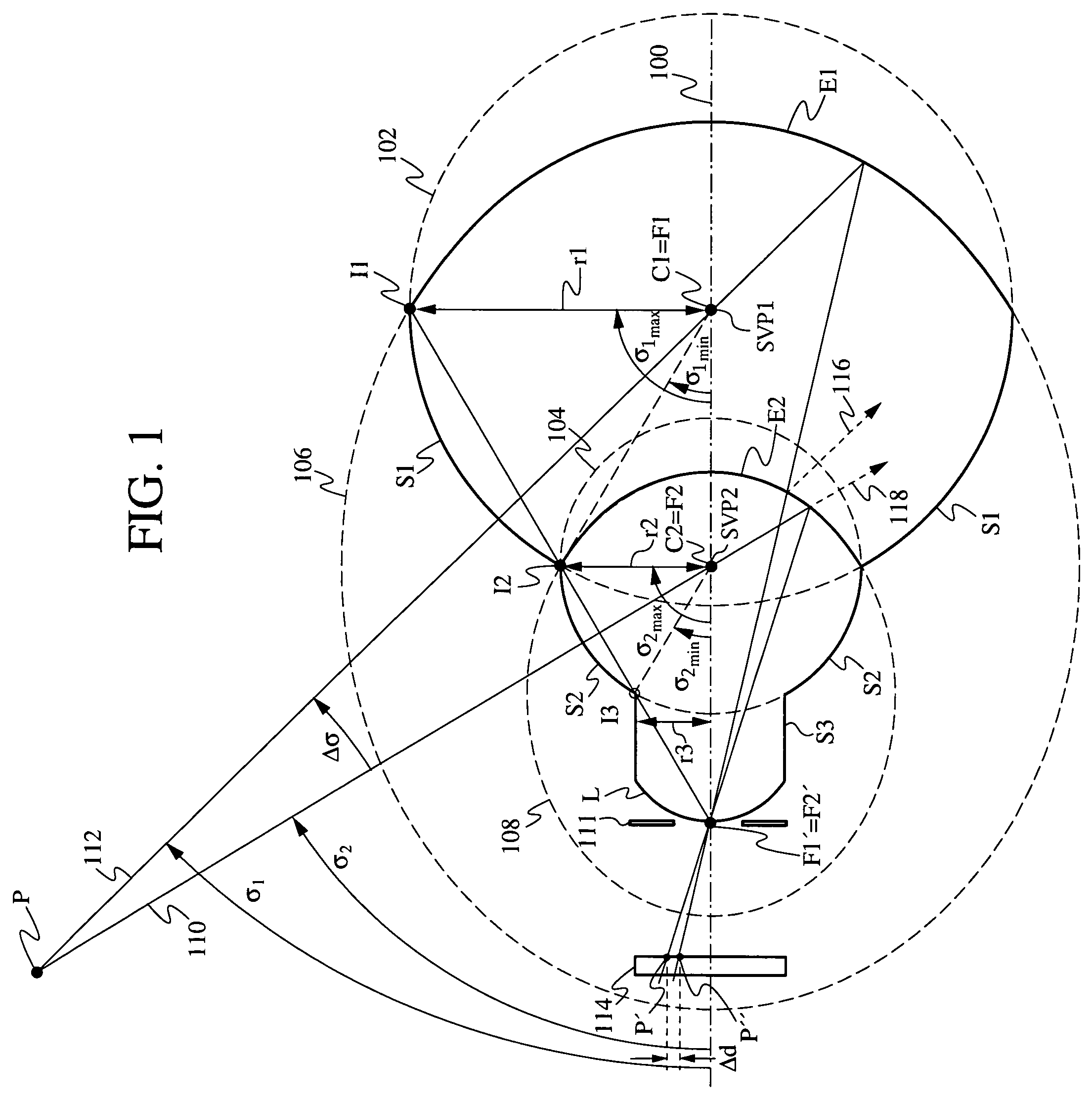
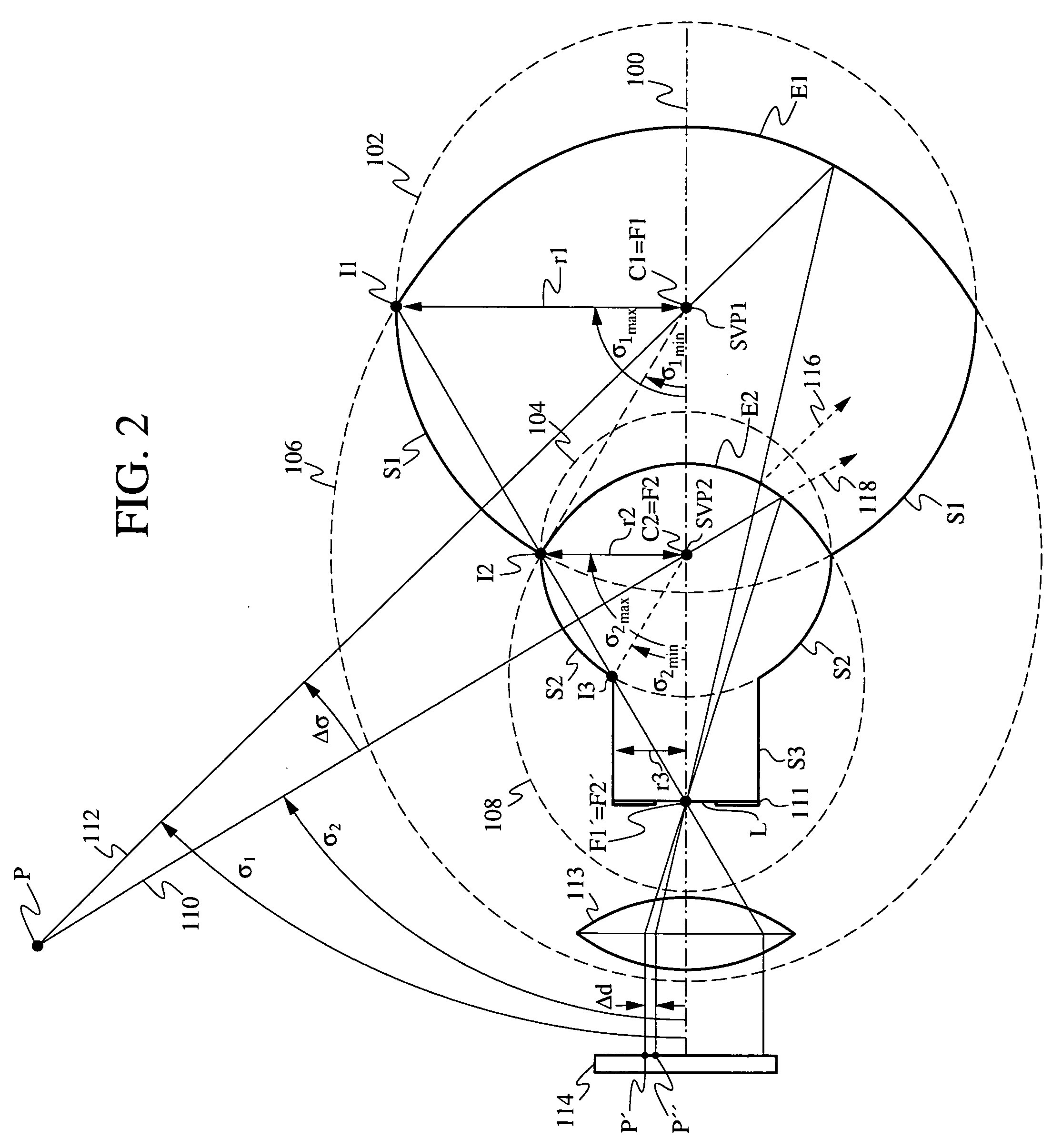
[0010]FIG. 1 is a cross-sectional view of a dual-viewpoint solid catadioptric lens according to an embodiment of the invention. The lens has a first spherical refractive surface S1 whose center C1 is located on an optical axis 100 of the lens. Surface S1 has a radius of curvature r1 which is the radius of dashed circle 102, which is shown in the figure to aid in the understanding of the lens geometry. The lens also has a second, smaller spherical refractive surface S2 whose center C2 is also located on the optical axis 100 of the lens. Surface S2 has a radius of curvature r2 which is the radius of circle 104. In this particular embodiment, the center C2 of the smaller circle 104 lies within the larger circle 102. In other words, the distance between centers C1 and C2 is less than radius r1. In other embodiments, the center C2 may lie outside the larger circle 102, i.e., the distance between C1 and C2 is greater than r1.

[0011]The lens has a first ellipsoidal reflective surface E1 who...


PUM


Abstract

A dual viewpoint solid catadioptric lens has a first spherical refractive surface S1 having a center C1 located on an optical axis of the lens and having a radius r1, and a second spherical refractive surface S2 having a center C2 located on the optical axis of the lens and having a radius r2<r1. The lens also has a first ellipsoidal reflective surface E1 with foci F1 and F1′ on the optical axis of the lens, and a second ellipsoidal partially reflective surface E2 having foci F2 and F2′ on the optical axis of the lens. Focus F1 coincides with C1, focus F2 conincides with C2, and focus F1′ coincides with F2′. The points C1 and C2 provide dual viewpoints for the lens, which may be used in a variety of imaging applications.

Description

CROSS-REFERENCE TO RELATED APPLICATIONS[0001]This application is a continuation-in-part of U.S. patent application Ser. No. 10 / 721,194, filed Nov. 24, 2003 now U.S. Pat. No. 7,038,846. This application also claims priority from U.S. Prov. Pat. Appl. No. 60 / 716,890, filed Sep. 14, 2005. Both applications are incorporated herein by reference.FIELD OF THE INVENTION[0002]The present invention relates generally to optical lenses, and more particularly to solid catadioptric lenses with two viewpoints.BACKGROUND OF THE INVENTION[0003]Catadioptric lenses are well-known in computer vision and imaging systems, robotic sensors, and various other applications. Each imaging application typically has specific design requirements, resulting in many different types of catadioptric lenses. Unfortunately, many wide-angle lenses and optical systems are complex and expensive.[0004]For example, U.S. Pat. No. 6,449,103 discloses a variety of complicated wide-angle lens systems. U.S. Pat. No. 5,473,474 to...

Claims


Application Information

Patent Timeline
Patent Type & Authority Patents(United States)
IPC IPC(8): G02B17/08
CPCG02B3/00G02B13/16G02B17/0808G02B17/086G02B17/0896
Inventor MANDELLA, MICHAEL J.
Owner ELECTRONICS SCRIPTING PRODS
Why Eureka
Try Eureka