Remote antenna unit and wavelength division multiplexing radio-over-fiber network

a radio-over-fiber network and wavelength division technology, applied in the field of optical networks, can solve the problems of increasing the cost of realizing the network, complicated networks, and limitations of the wavelength division multiplexing radio-over-fiber network b>100/b> described above, and achieve the effect of simple structure and low cos

Inactive Publication Date: 2007-09-11
SAMSUNG ELECTRONICS CO LTD
View PDF4 Cites 142 Cited by
  • Summary
  • Abstract
  • Description
  • Claims
  • Application Information

AI Technical Summary

Benefits of technology

[0034]Accordingly, the present invention has been made to reduce or overcome the above-mentioned problems occurring in the prior art and provides additional advantages, by providing a remote antenna unit that has a simple structure and a lower cost for realizing the remote antenna unit.
[0035]Another object of the present invention is to provide a wavelength division multiplexing radio-over-fiber network which can increase the efficiency of the wavelength band using the remote antenna unit.

Problems solved by technology

Moreover, the wavelength division multiplexing radio-over-fiber network allows complicated electric devices dispersed in a plurality of base stations to be concentrated in a central office.
However, the conventional wavelength division multiplexing radio-over-fiber network 100 described above has a number of limitations.
Thus, the network is complicated and the cost of realizing the network is increased.
Further, the upstream wavelength band and downstream wavelength band must be separate, thereby decreasing the efficient use of the wavelength band.

Method used


Image

  • Remote antenna unit and wavelength division multiplexing radio-over-fiber network
  • Remote antenna unit and wavelength division multiplexing radio-over-fiber network
  • Remote antenna unit and wavelength division multiplexing radio-over-fiber network

Examples


Embodiment Construction

[0044]Hereinafter, embodiments of the present invention will be described in detail with reference to the accompanying drawings. For the purposes of clarity and simplicity, a detailed description of known functions and configurations incorporated herein will be omitted to avoid making the subject matter of the present invention unclear.

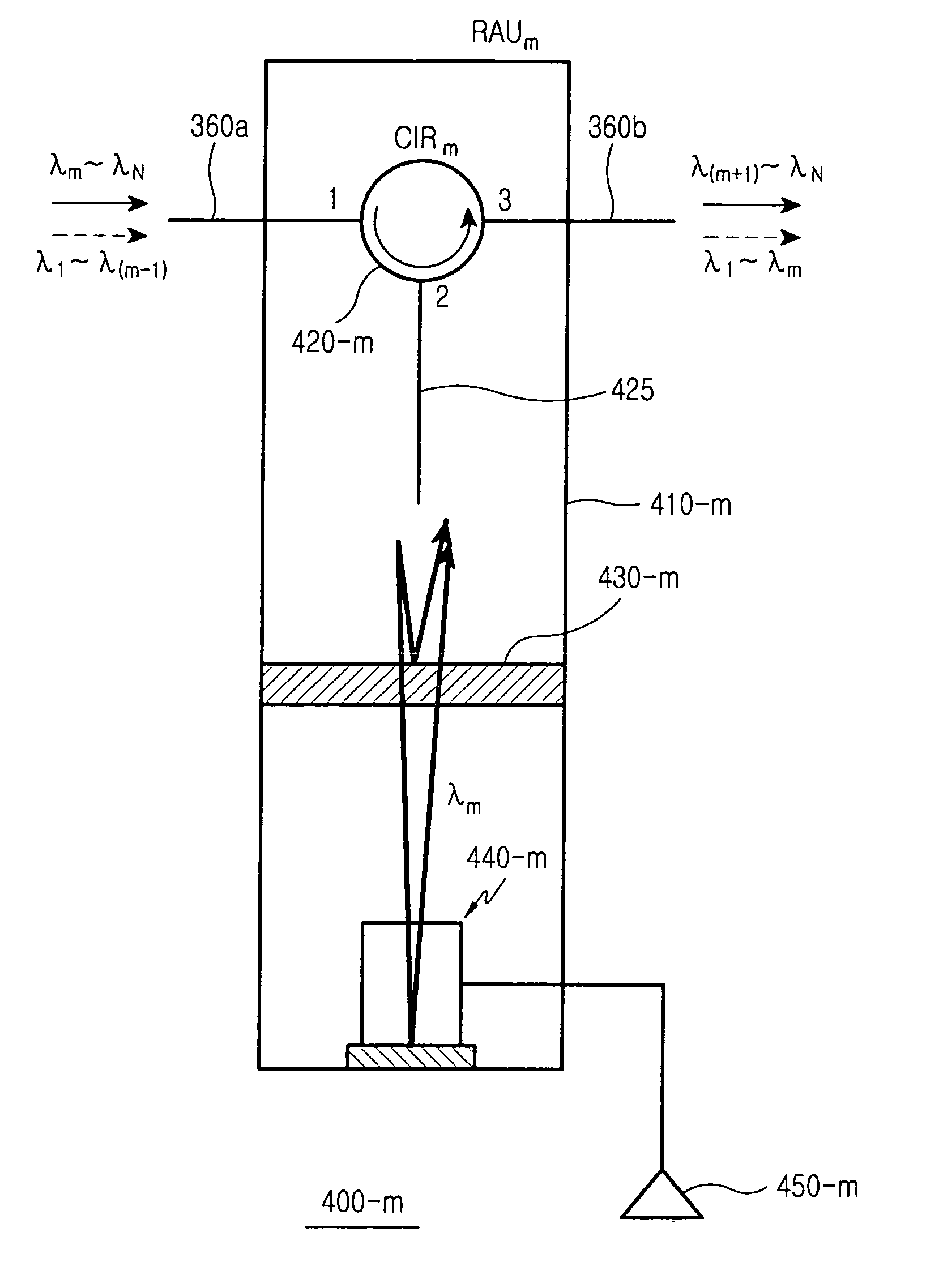
[0045]FIG. 3 is a block diagram of a wavelength division multiplexing radio-over-fiber network according to a preferred embodiment of the present invention. The radio-over-fiber network 300 includes a base station 310, and first, second, third, . . . , and Nth remote antenna units 400-1, 400-2, 400-3, . . . , and 400-N connected to the base station 310 through an optical fiber 360 in order and in a loop structure.

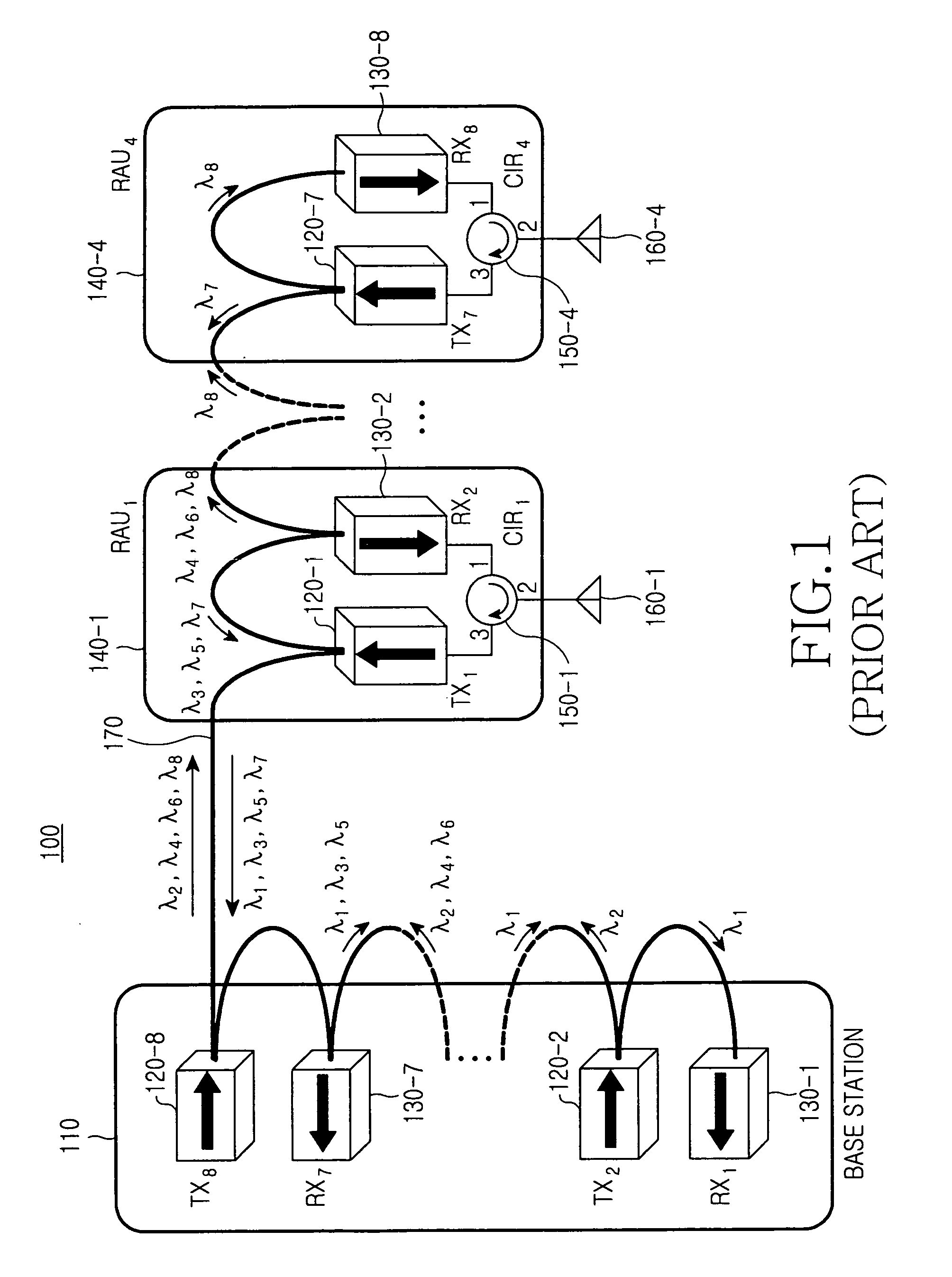
[0046]The base station 310 includes an optical transmission portion 312 having first, second, third, . . . , and Nth optical transmitters 320-1, 320-2, 320-3, . . . , 320-N and a first wavelength division multiplexer 330, and an optical recep...


PUM


Abstract

Disclosed is a remote antenna unit and a wavelength division multiplexing network. The remote antenna unit includes: an optical circulator having a plurality of ports; an electric field absorption modulator having a first input / output end and a second reflective end, the electric field absorption modulator configured to demodulate an optical signal into a first data signal, and modulate the demodulated optical signal according to a second electric data signal; and a filter disposed between the optical circulator and the electric field absorption modulator, for the filter configured to transmit an optical signal having a particular wavelength from among optical signals input from a port of the optical circulator toward the electric field absorption modulator and reflecting the remaining optical signals into the port of the optical circulator, and inputting the optical signal from the electric field absorption modulator into the port of the optical circulator.

Description

CLAIM OF PRIORITY[0001]This application claims priority to an application entitled “Remote Antenna Unit and Wavelength Division Multiplexing Radio-Over-Fiber Network Using the Same” filed with the Korean Intellectual Property Office on Apr. 4, 2005 and assigned Serial No. 2005-0028147, the contents of which is incorporated herein by reference.BACKGROUND OF THE INVENTION[0002]1. Field of the Invention[0003]The present invention relates to an optical network, and more particularly to a wavelength division multiplexing radio-over-fiber network that supports bidirectional wireless communication.[0004]2. Description of the Related Art[0005]A radio-over-fiber network transmits radio signals through optical fibers. In particular, an optical transmitter converts radio signals into optical signals and transmits the optical signals through the optical fibers. An optical receiver converts optical signals received through the optical fibers into radio signals. When wavelength division multiplex...

Claims


Application Information

Patent Timeline
Patent Type & Authority Patents(United States)
IPC IPC(8): G02B6/26
CPCH04B10/25755H04B10/2575H04B10/2581
Inventor KIM, YONG-GYOOLEE, GYU-WOONGHWANG, SEONG-TAEK
Owner SAMSUNG ELECTRONICS CO LTD
Why Eureka
Try Eureka