Receiver of double conversion system with antenna tuning with variable capacitance using digital-to-analog converter having temperature coefficient setting section

a technology of temperature coefficient and receiver, which is applied in the direction of multi-frequency-changing modulation transference, multi-resonant circuit tuned to different frequencies, resonant circuits using central processing units, etc. it can solve the problems of increasing the number of components, unwanted components, antennas, etc., and reducing the number of components , the effect of facilitating the change of output voltag

Inactive Publication Date: 2007-09-11
NIIGATA SEIMITSU
View PDF21 Cites 2 Cited by
  • Summary
  • Abstract
  • Description
  • Claims
  • Application Information

AI Technical Summary

Benefits of technology

[0005]The present invention has been made in view of the above-described circumstances. An object of the present invention is to provide a receiver of double conversion system capable of surely removing unwanted components included in a received signal, and of reducing the number of components.
[0006]In order to solve the above-described problem, according to the present invention, there is provided a receiver of double conversion system comprising: an antenna tuning circuit including a tuning coil and a variable-capacitance diode; a high frequency amplification circuit for performing high frequency amplification for a signal outputted from the antenna tuning circuit; first and second mixing circuits for performing frequency conversion twice for an output of the high frequency amplification circuit; and a detecting circuit for performing detection processing for an output of the mixing circuits. The double conversion system adopted and the antenna tuning circuit provided in a former stage of the high frequency amplification circuit make it possible to surely remove unwanted components, such as a radio wave of an undesired broadcasting station and a noise, etc. which are included in the received broadcast wave. Since the tuning coil in the antenna tuning circuit can be used as an antenna, as compared with the case where the tuning circuit is provided for a subsequent stage of high frequency amplification circuit, the coil for tuning and the antenna need not be provided separately, so that the number of components can be reduced.
[0007]The above-described first mixing circuit also preferably converts a frequency of a signal outputted from the high frequency amplification circuit to a frequency higher than the frequency of the broadcast wave, and the second mixing circuit preferably converts a frequency of a signal outputted from the first mixing circuit to a frequency lower than the frequency of the broadcast wave, thereby enabling image interference included in the received broadcast wave to be easily removed.

Problems solved by technology

In the receiver disclosed in Japanese Patent Laid-Open No. 2000-174653 described above, however, since the signal received via the antenna is made to pass the tuning circuit after being subjected to the high frequency amplification, there is a problem in that unwanted components such as a radio wave of a broadcasting station whose reception is not desired and a noise, when included in the signal received by the antenna, are also amplified.
For example, a rod antenna is generally used as the antenna, but in this case, there is a problem in that both the rod antenna and the tuning coil are needed, causing the number of components to be increased.

Method used


Image

  • Receiver of double conversion system with antenna tuning with variable capacitance using digital-to-analog converter having temperature coefficient setting section
  • Receiver of double conversion system with antenna tuning with variable capacitance using digital-to-analog converter having temperature coefficient setting section
  • Receiver of double conversion system with antenna tuning with variable capacitance using digital-to-analog converter having temperature coefficient setting section

Examples


Embodiment Construction

[0021]Hereafter, a receiver of an embodiment in which a double conversion system according to the present invention is adopted will be described with reference to the accompanying drawings.

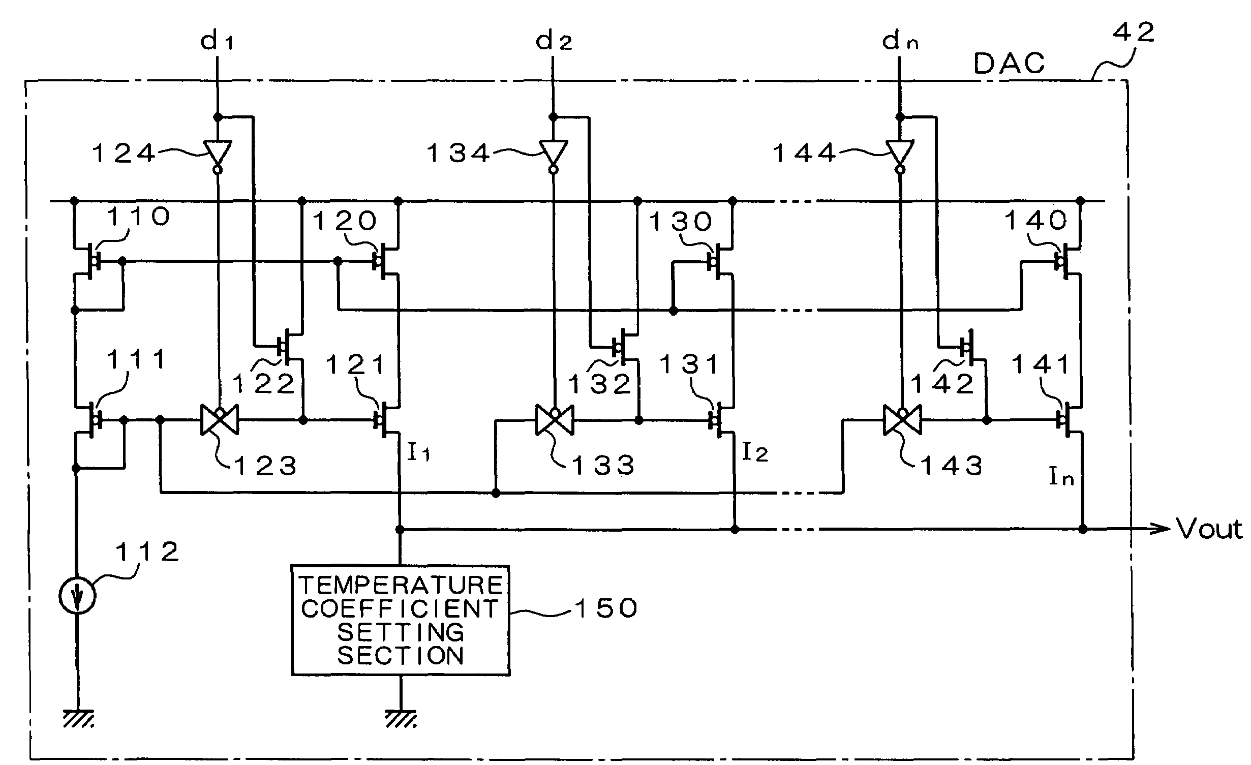
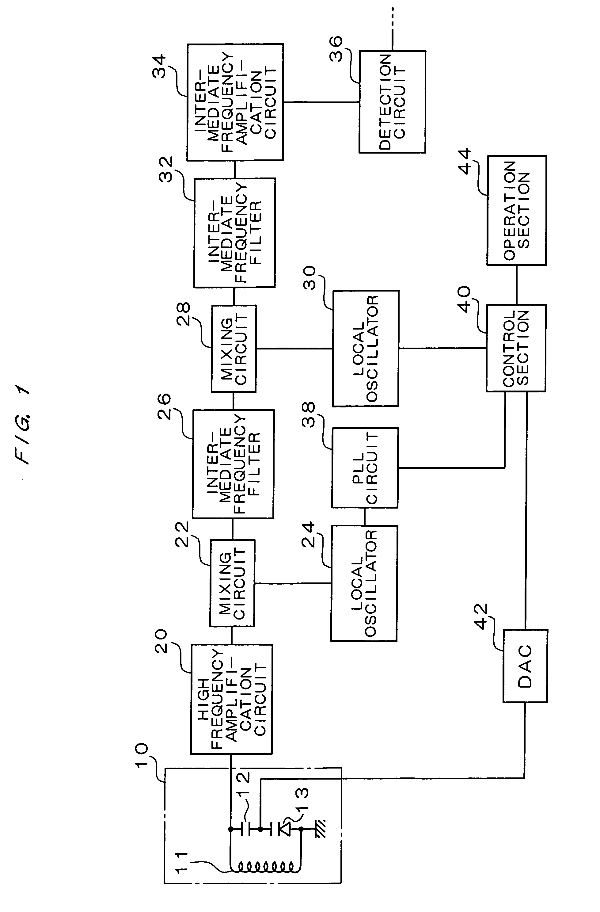
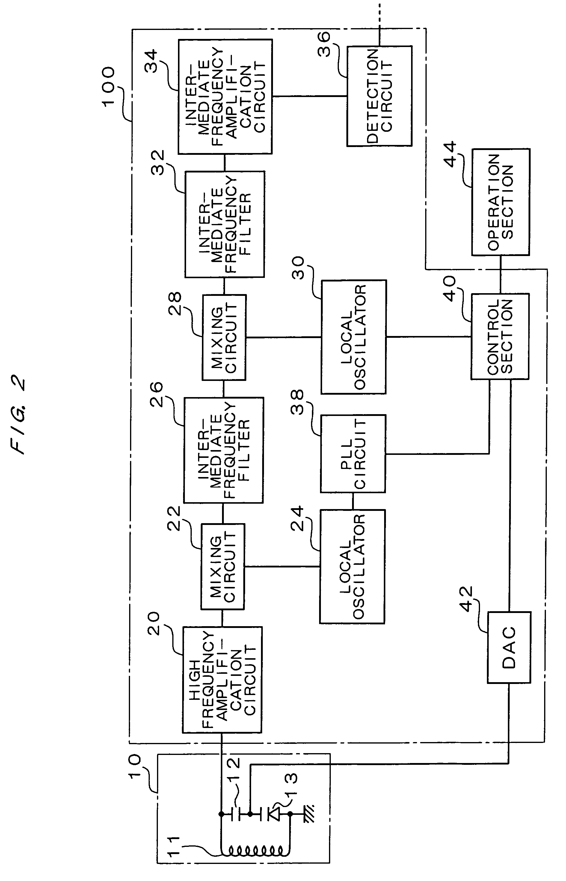
[0022]FIG. 1 is a figure showing a configuration of a receiver according to a first embodiment. The receiver of double conversion system according to the first embodiment shown in FIG. 1 is constituted by including an antenna tuning circuit 10, a high frequency amplification circuit 20, mixing circuits 22, 28, local oscillators 24, 30, intermediate frequency filters 26, 32, an intermediate frequency amplification circuit 34, a detecting circuit 36, a PLL circuit 38, a control section 40, a DAC (digital-analog converter) 42, and an operation section 44.

[0023]The antenna tuning circuit 10 is constituted by a tuning coil 11, a capacitor 12 and a variable-capacitance diode 13. The tuning coil 11 and the variable-capacitance diode 13 are connected in parallel, and their parallel resonance frequency is ...


PUM


Abstract

A receiver of double conversion system wherein unwanted components included in received signals can be removed without fail and wherein the number of constituent parts has been reduced. The receiver comprises an antenna tuning circuit 10 including a tuning coil 11 and a variable-capacitance diode 13; a high frequency amplification circuit 20 for performing a high frequency amplification of a signal outputted by the antenna tuning circuit 10; two-stage mixing circuits 22, 28 for performing two frequency conversions of an output from the high frequency amplification circuit 20; and a detecting circuit 36 for detecting an output from the latter-stage mixing circuit 28.

Description

TECHNICAL FIELD[0001]The present invention relates to a receiver of double conversion system for performing frequency conversion two times.BACKGROUND ART[0002]A receiver of double conversion system for performing frequency conversion two times for a received broadcast wave by using two mixing circuits is conventionally known (for example, see pages 2 to 3, FIGS. 1 to 4 of Japanese Patent Laid-Open No. 2000-174653). The first stage mixing circuit converts the broadcast wave to a higher frequency signal so as to enable image interference to be easily removed, as a result of which excellent interference characteristics can be realized with a non-tuning type receiver without an antenna tuning circuit and an RF tuning circuit.[0003]In the above-described patent gazette document, a prior art is also disclosed in which the reception sensitivity and the interference characteristic are further improved in the receiver of double conversion system by making a signal obtained by applying high f...

Claims


Application Information

Patent Timeline
Patent Type & Authority Patents(United States)
IPC IPC(8): H04B1/18H04B1/26H03D7/16H03J1/00H03J3/28H04B1/10H04B1/28
CPCH04B1/1027H03D7/163H04B1/28H03J1/0008
Inventor MIYAGI, HIROSHIKATSUNAGA, HIROSHI
Owner NIIGATA SEIMITSU
Why Eureka
Try Eureka