Selectively monitoring loads to support transactional program execution

a transactional program and load technology, applied in the direction of program control, multi-programming arrangement, memory adressing/allocation/relocation, etc., can solve the problem of synchronization overhead becoming the dominant factor in limiting application performance, the process of acquiring a lock and releasing a lock is very time-consuming in the modem microprocessor, and achieves the effect of facilitating subsequent detection of an interfering data access

Active Publication Date: 2007-09-11
ORACLE INT CORP
View PDF24 Cites 61 Cited by
  • Summary
  • Abstract
  • Description
  • Claims
  • Application Information

AI Technical Summary

Benefits of technology

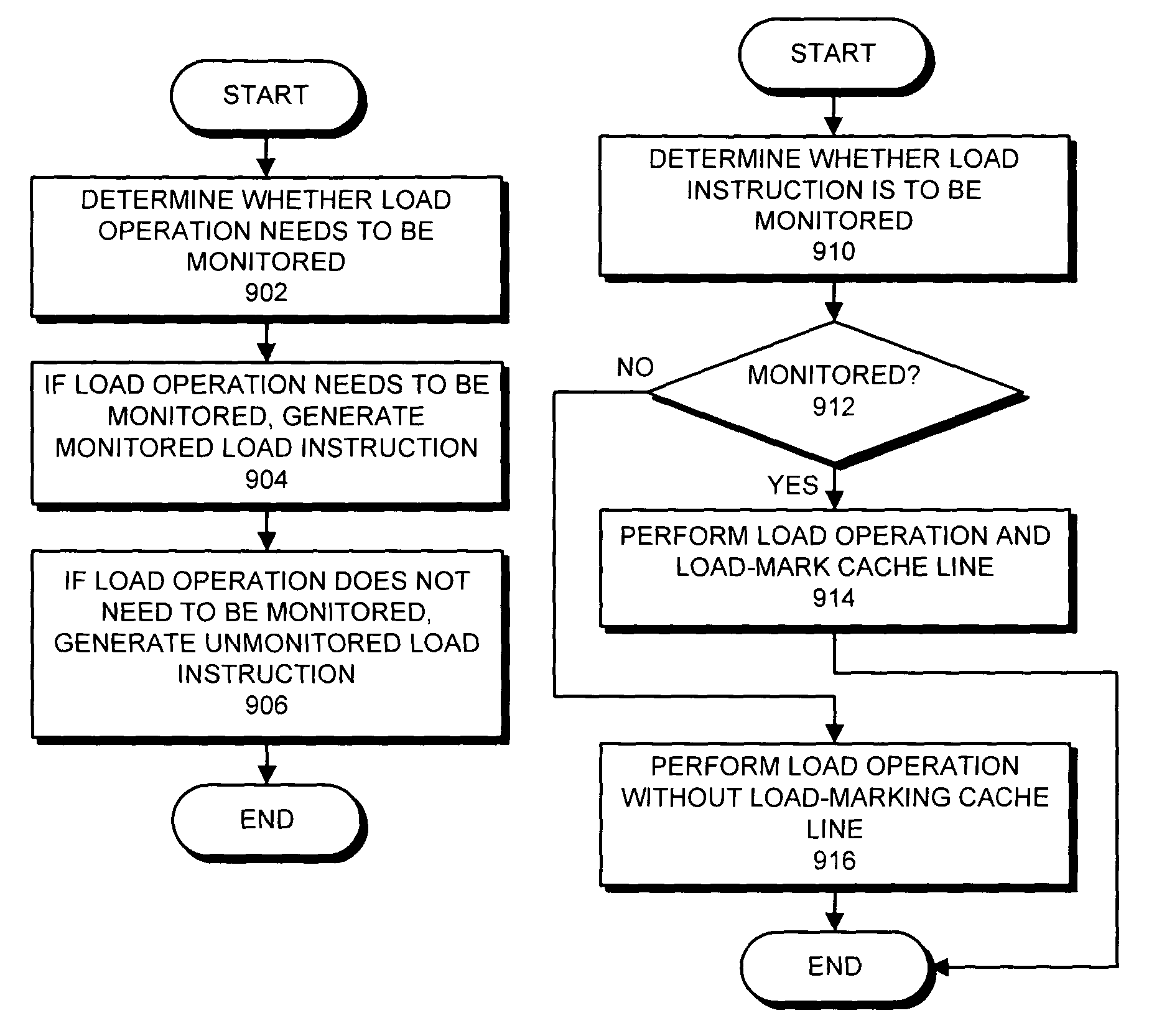
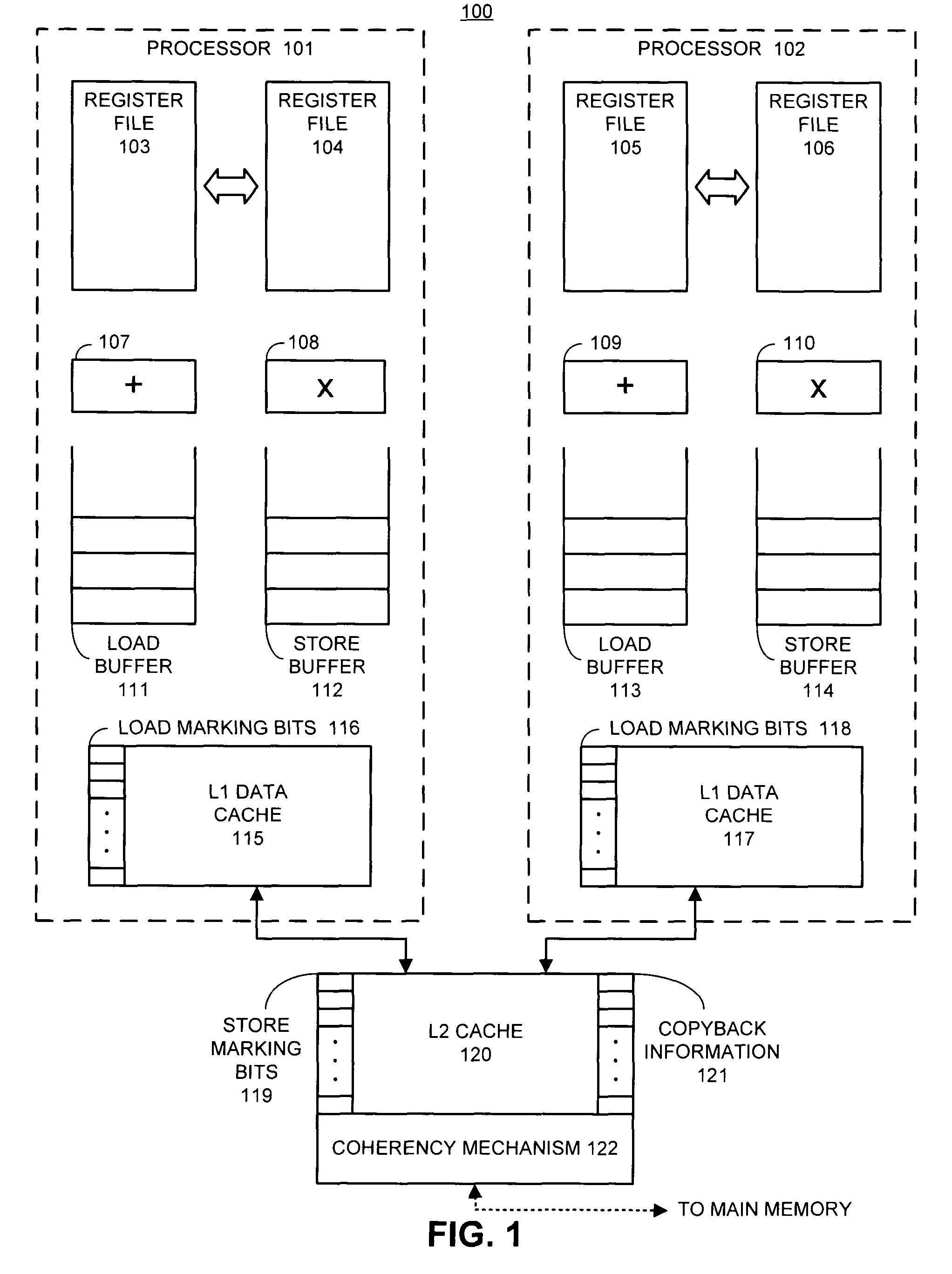
[0018]One embodiment of the present invention provides a system that selectively monitors load instructions to support transactional execution of a process, wherein changes made during the transactional execution are not committed to the architectural state of a processor until the transactional execution successfully completes. Upon encountering a load instruction during transactional execution of a block of instructions, the system determines whether the load instruct

Problems solved by technology

However, as microprocessor performance continues to increase, the time spent synchronizing between threads (processes) is becoming a large fraction of overall execution time.
In fact, as multi-threaded applications begin to use even more threads, this synchronization overhead becomes the dominant factor in limiting application performance.
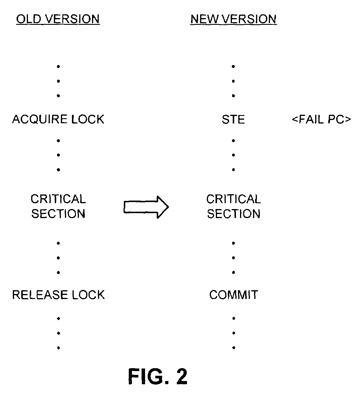
Unfortunately, the process of acquiring a lock and the process of releasing a lock are very time-consuming in modem microprocessors.
They involve atomic operations, which typically flush the load buffer and store buffer, and can consequently require hundreds, if not thousands, of processor cycles to complete.
For example, if multiple threads need to access a shared data structure, it is impractical for performance reasons to use a single lock for the entire data structure.
Unfortunately, the overhead inv

Method used


Image

  • Selectively monitoring loads to support transactional program execution
  • Selectively monitoring loads to support transactional program execution
  • Selectively monitoring loads to support transactional program execution

Examples


Embodiment Construction

[0050]The following description is presented to enable any person skilled in the art to make and use the invention, and is provided in the context of a particular application and its requirements. Various modifications to the disclosed embodiments will be readily apparent to those skilled in the art, and the general principles defined herein may be applied to other embodiments and applications without departing from the spirit and scope of the present invention. Thus, the present invention is not intended to be limited to the embodiments shown, but is to be accorded the widest scope consistent with the principles and features disclosed herein.

[0051]The data structures and code described in this detailed description are typically stored on a computer readable storage medium, which may be any device or medium that can store code and / or data for use by a computer system. This includes, but is not limited to, magnetic and optical storage devices such as disk drives, magnetic tape, CDs (...


PUM


Abstract

One embodiment of the present invention provides a system that selectively monitors load instructions to support transactional execution of a process, wherein changes made during the transactional execution are not committed to the architectural state of a processor until the transactional execution successfully completes. Upon encountering a load instruction during transactional execution of a block of instructions, the system determines whether the load instruction is a monitored load instruction or an unmonitored load instruction. If the load instruction is a monitored load instruction, the system performs the load operation, and load-marks a cache line associated with the load instruction to facilitate subsequent detection of an interfering data access to the cache line from another process. If the load instruction is an unmonitored load instruction, the system performs the load operation without load-marking the cache line.

Description

RELATED APPLICATION[0001]This application hereby claims priority under 35 U.S.C. §119 to U.S. Provisional Patent Application No. 60 / 447,128, filed on 13 Feb. 2003, entitled “Transactional Memory,” by inventors Shailender Chaudhry, Marc Tremblay and Quinn Jacobson.[0002]The subject matter of this application is additionally related to the subject matter in a co-pending non-provisional U.S. patent application by the same inventors as the instant application and filed on the same day as the instant application entitled, “Selectively Monitoring Stores to Support Transactional Program Execution,” having Ser. No. 10 / 637,167, and filing date 8 Aug. 2003.BACKGROUND[0003]1. Field of the Invention[0004]The present invention relates to techniques for improving the performance of computer systems. More specifically, the present invention relates to a method and an apparatus for selectively monitoring loads to support transactional program execution.[0005]2. Related Art[0006]Computer system desi...

Claims


Application Information

Patent Timeline
IPC IPC(8): G06F12/14G06F9/46G06F12/08
CPCG06F9/3004G06F9/30087G06F9/3834G06F9/467G06F12/0815G06F12/0862G06F9/3857G06F12/0842G06F9/3836G06F9/3858
Inventor TREMBLAY, MARCJACOBSON, QUINN A.CHAUDHRY, SHAILENDER
Owner ORACLE INT CORP
Why Eureka
Try Eureka