
Deep draft semisubmersible movable offshore structure

Inactive Publication Date: 2007-09-18
BENNU OIL & GAS LLC
View PDF10 Cites 9 Cited by
  • Summary
  • Abstract
  • Description
  • Claims
  • Application Information

AI Technical Summary

Benefits of technology

[0007]It is therefore, an object of the present invention to provide a deep draft partially submersible and buoyant offshore rig with inherent absolute stability and minimum movement, that not only has reduced heave and roll motion to affect risers connected to it from the sea floor, but equipment to significantly reduce yaw, roll, and sway on risers coming from a subsea well at a large water depth, such as 5000 feet, 8000 feet or even 10,000 feet.
[0014]The columns are spaced from each other to provide wave transparency and afloat stability for damping wave induced motions of the vessel and all of the ballast means accommodating eccentricities acting on the deck and / or operational loads so as to prevent mutual load transfer between the columns. A plurality of horizontal braces can be used to prevent mutual load transfer.
[0017]Bracing members are fixedly connected to each column and to the tensioner assembly. Some of the bracing members are located at a plurality of spaced vertical locations along the length of the columns. The bracing members are used to reduce water plane inertia to said vessel and to provide stability of the vessel deployed at an offshore location.

Problems solved by technology

Still fewer structures can perform drilling, production, and workover operations in deep waters, far from shore.

Method used


Image

  • Deep draft semisubmersible movable offshore structure
  • Deep draft semisubmersible movable offshore structure
  • Deep draft semisubmersible movable offshore structure

Examples


Embodiment Construction

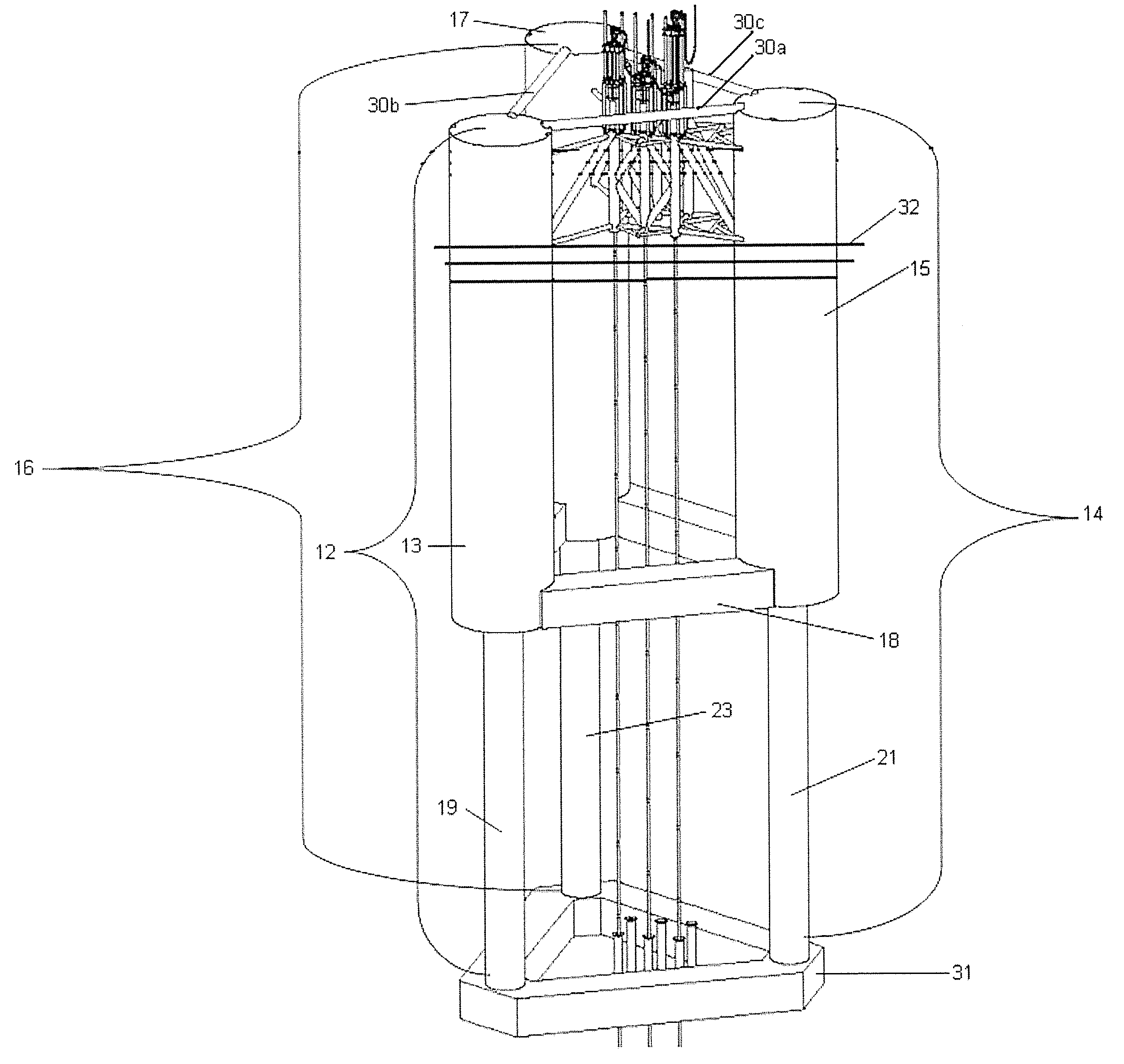
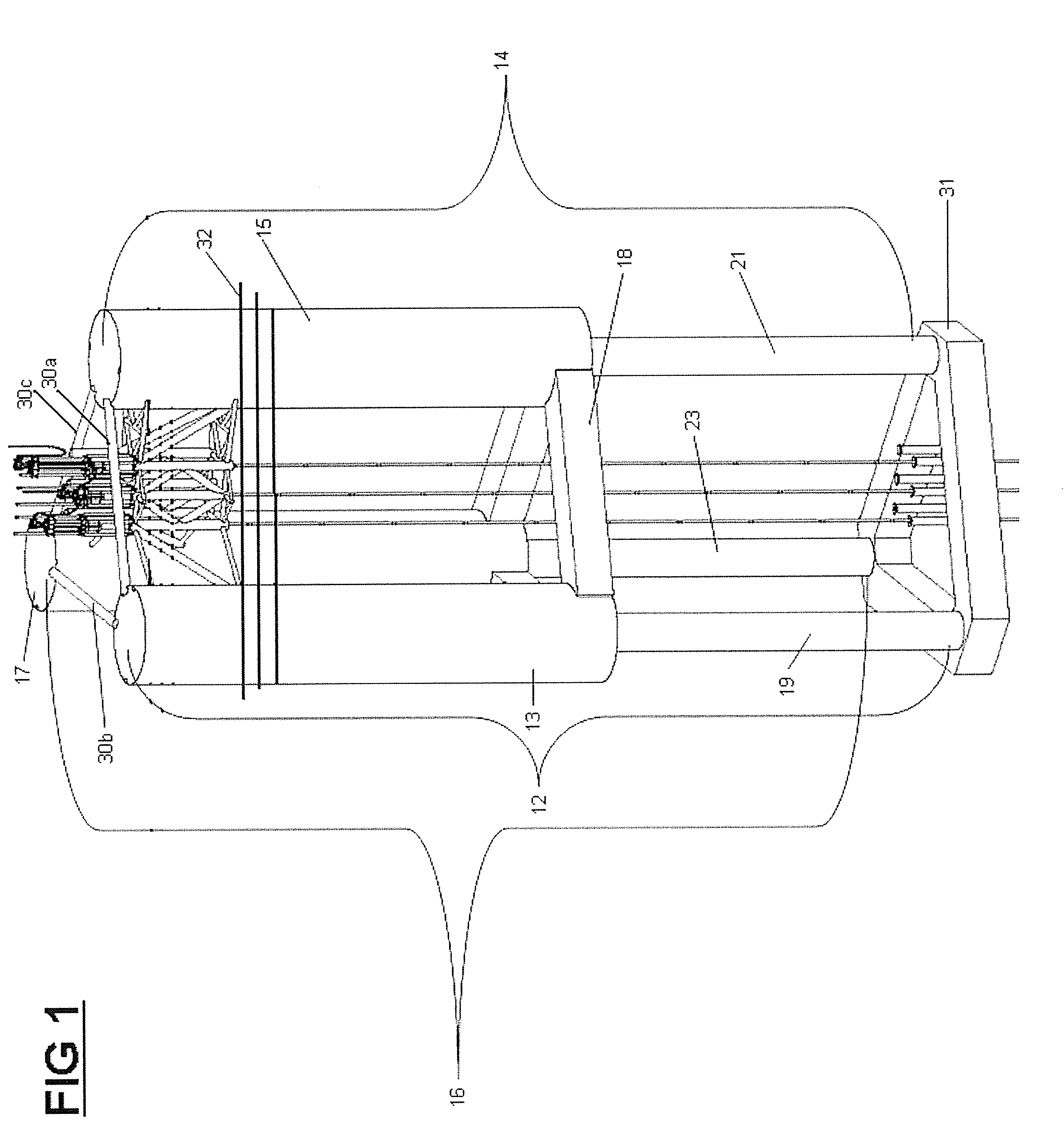
[0035]Referring now to FIG. 1, FIG. 1 depicts a portion of an embodiment of the offshore rig in accordance with the present invention, hereafter termed the “rig.”

[0036]The rig of this depicted embodiment is made of three columns, 12, 14, and 16 spaced geometrically in a triangular configuration.

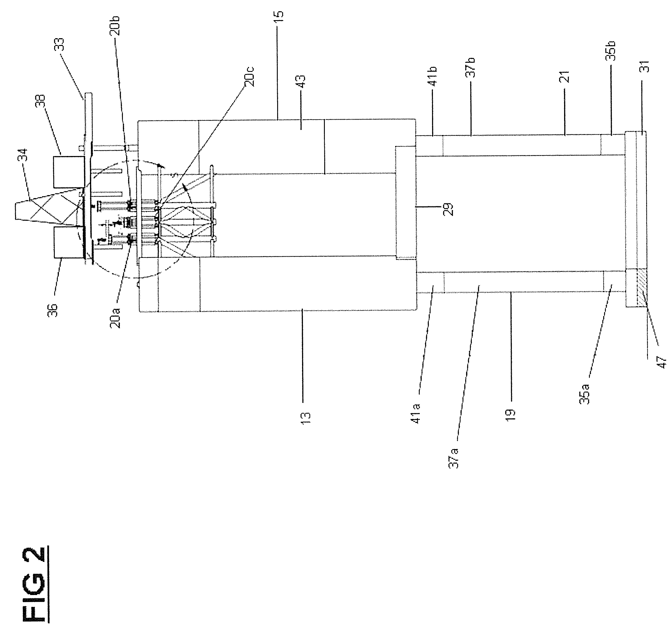
[0037]It is contemplated that more than three columns can be used, such as four columns geometrically spaced in a square or rectangular configuration, eight columns spaced in an octagonal configuration, or other numbers of columns and configurations. The columns 12, 14, and 16 are connected together, forming a central hole 18 over which a tensioner assembly 20, shown in FIG. 2, can be positioned for holding risers from the sea floor.

[0038]The columns 12, 14 and 16 are submerged below the water surface 32 to a depth sufficient to remove the influence of surface waves.

[0039]In an embodiment, it is contemplated that the submerged portion of each column would occupy between 30% and 80% of the len...


PUM


Abstract

The present invention is a deep draft partially submersible and buoyant floating vessel comprised of at least three independent vertical columns. The columns have an upper column with an upper column diameter and a lower column integrally connected to the upper column with a lower column diameter smaller than the upper column diameters. The lower column contains a variable ballast, a free flooding ballast, and a lower column fixed ballast. The lower pontoon is connected to each lower column opposite the upper column. The lower pontoon has lower pontoon fixed ballast means. A deck is located on the columns for supporting a tensioner assembly.

Description

FIELD[0001]The present embodiments relate generally to a moveable, towable, submersible floating offshore vessel suitable for use in deep waters for supporting, oil and gas drilling, production, and workover operations.BACKGROUND[0002]Many types of structures exist for oil and gas exploration, however few exist that can perform drilling and production operations and be moveable. Still fewer structures can perform drilling, production, and workover operations in deep waters, far from shore.[0003]A need has existed for an improved, versatile vessel that can be used for demanding drilling operations in deep waters, yet be a floating vessel that can be towed from site to site for work.[0004]Additionally, a need has existed for a vessel that is transparent to the motion of the waves about the lower portions of the rig, while having a center of gravity below the center of buoyancy to reduce the effects of heave and roll motion during use.[0005]A need has existed for a rig that can additio...

Claims


Application Information

Patent Timeline
IPC IPC(8): B63B35/44
CPCB63B35/4406
Inventor SHIVERS, III, ROBERT M.BENNETT, JR., WILLIAM T.TRENT, DAVID
Owner BENNU OIL & GAS LLC
Learn More