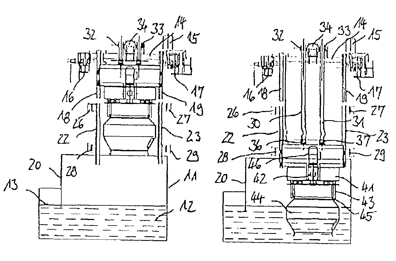
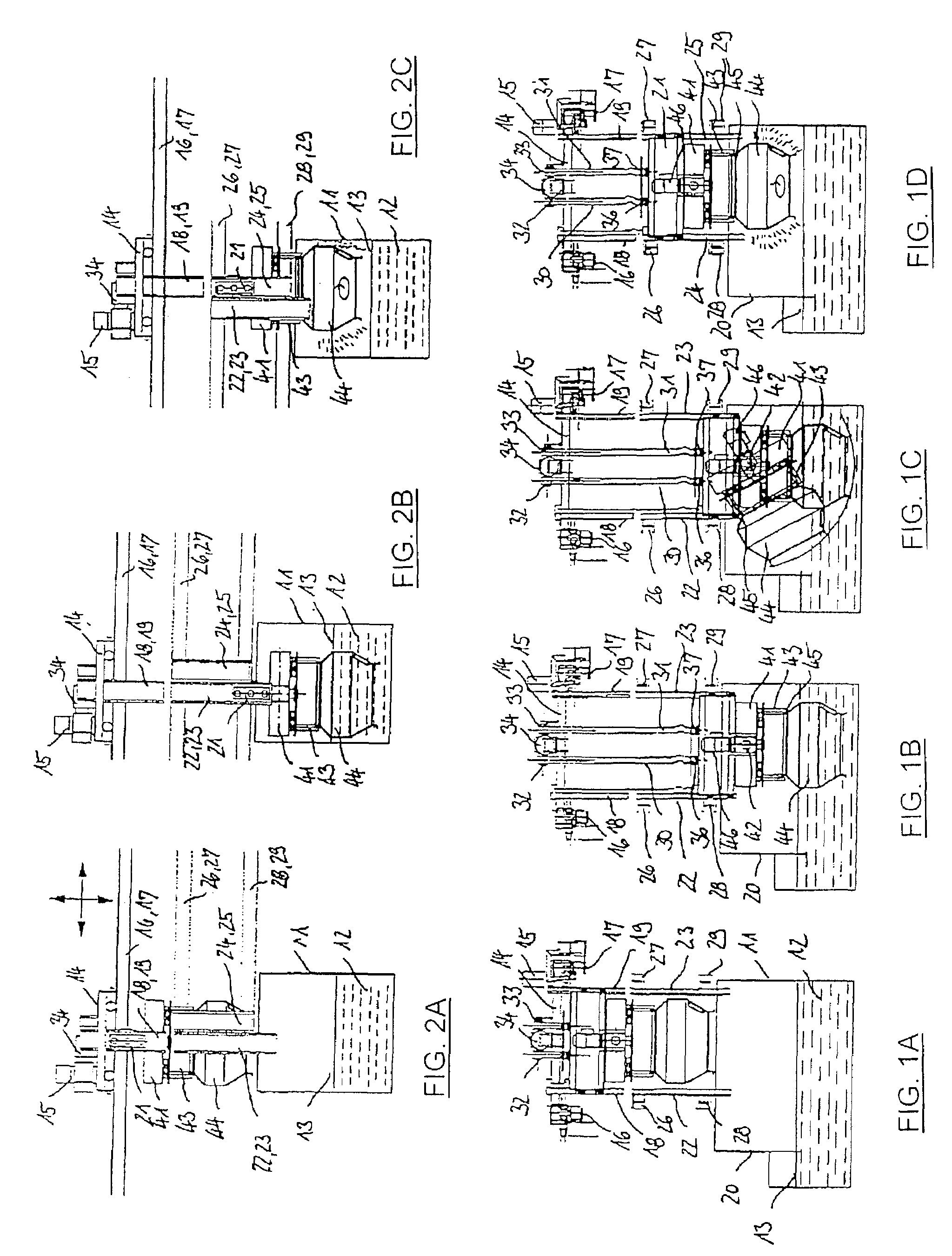
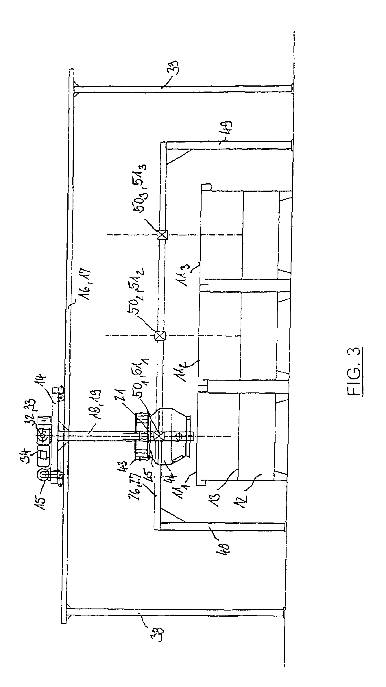
[0005]It is an object of the present invention to provide a system for treating, in liquid, mass-production parts contained in transport baskets, which system incorporates the features of the initially mentioned type with
fully developed treatment machines, but which has a simplified design. In this regard, the present invention provides a system for treating, in liquid, mass-production parts contained in transport baskets, comprising at least one tank which contains liquid for submerging the transport basket, at least one transport vehicle for the transport baskets, by means of which transport vehicle the transport baskets can be moved over the at least one tank, at least one basket carrier which is arranged at the transport vehicle in such a way that its height can be adjusted. The basket carrier is able to grip a transport basket, submerge same in the tank and lift same out of the tank, and is able to rotatingly drive the transport basket around an axis. The system also includes a clamping mechanism for clamping the basket carrier relative to fixed parts near the at least one tank. The clamping mechanism make it possible to securely support the basket carrier relative to a treatment tank in order to be able to drive heavy transport baskets which, when filled, may be out-of-balance, around their axes at a rotational speed which has to be increased to be able to spin off the liquid. In particular, clamping can take place in two different positions: on the one hand, with the transport basket being immersed in the liquid underneath the surface of the liquid to be able to carry out washing and rinsing processes at a low rotational speed and, on the other hand, with the transport basket being suspended above the surface of the liquid in order to carry out a centrifuging process at an increased rotational speed. In an advantageous way, it is possible to eliminate the process of pumping off the treatment liquid such as it is necessary for centrifuging purposes with treatment machines with a firmly installed drum drive and with only one clamping position. Particularly, in the case of systems for treating mass-production parts involving a number of different cleaning,
coating or treatment stages with different liquids, it is advantageous that there is required only one row of simple tanks containing the respective cleaning,
coating and treatment liquids, such that transport means and rotary driving means need to be provided only once at the transport vehicle.
[0008]According to a first design, the transport vehicle comprises first vertical guides and near the at least one tank, there are fixedly attached second vertical guides into which it is possible to transfer the slide if the first and second guides are aligned. The clamping mechanism can be made to be effective at least in one lower position wherein the transport basket is submerged in the liquid in the tank underneath the liquid level between the slide and the fixed second guides. In such a case, the first guides can be relatively short and the second fixed guides at the at least one tank can be guided upwardly by a suitable amount. The second guides should extend downwardly sufficiently far for allowing clamping in a lower position, with the transport basket being positioned underneath the surface of the liquid and, without fail, in a higher position above the unchanged surface of the liquid.
[0012]According to a preferred embodiment, the basket carrier comprises a radially feedable gripping mechanism for the transport basket. The gripping mechanism holds the transport basket on the circumference at least three times. The basket carrier comprises a rotary drive for the gripping mechanism, which rotary drive permits centrifuging at higher rotational speeds as well. A further improvement is provided wherein the basket carrier with the gripping mechanism can be pivoted around a horizontal pivot axis relative to the slide. This makes it possible to rotatingly drive the transport basket in an inclined position, in particular in a position where it is only partially immersed in liquid. As a result, there is achieved a more intense circulating movement of the mass-production parts inside the transport basket.
[0016]According to an alternative embodiment, the rotary drive can be a simple, fixed friction
gear drive in the region of the tank. The gripping mechanism can be kept closed by spring pretension, so that when the basket carrier is separated from the transport vehicle, there is no need for power to be supplied to the basket carrier.
[0017]The above mentioned ability to separate the basket carrier and transport vehicle from one another is advantageous in that several basket carriers can be handled by one single transport vehicle, so that if there is provided a plurality of tanks, some of these can be occupied simultaneously by a transport basket.


