Spare tire storage structure
a technology of storage structure and spare tire, which is applied in the directions of roofs, transportation and packaging, vehicle arrangements, etc., can solve the problem that the spare tire storage structure cannot be used in the vehicl
- Summary
- Abstract
- Description
- Claims
- Application Information
AI Technical Summary
Benefits of technology
Problems solved by technology
Method used
Image
Examples
first embodiment
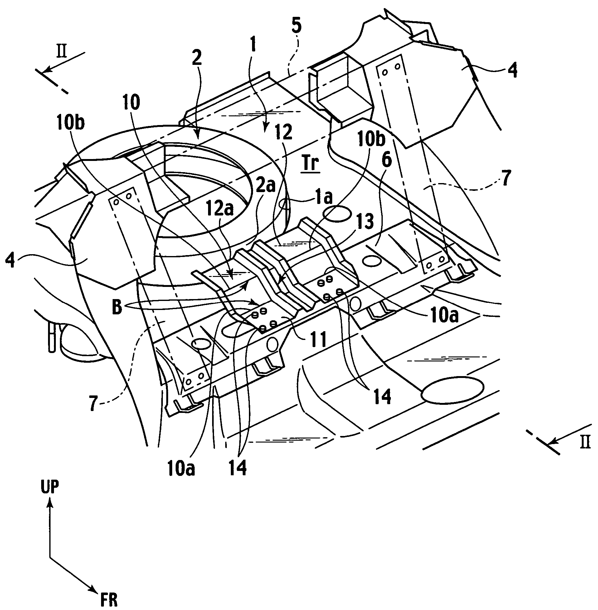
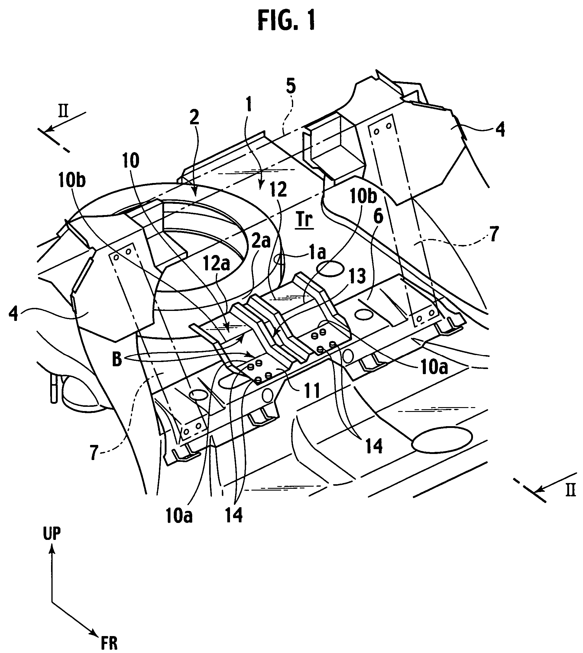
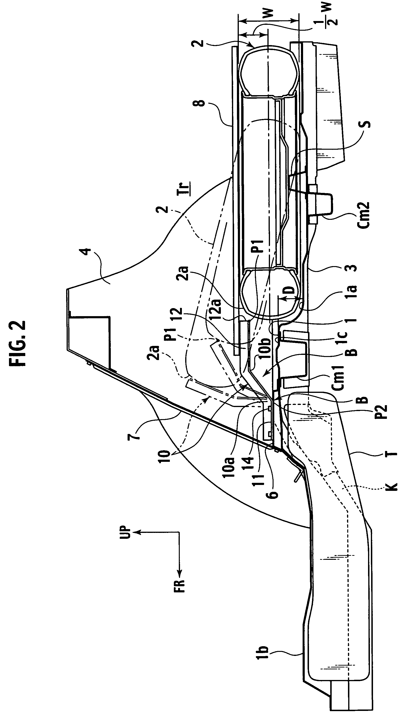
[0024]Referring to FIGS. 1 to 3, in a spare tire storage structure of the first embodiment, a spare tire 2 is stored in a center portion of a rear floor 1 in a vehicle transverse direction within a trunk room Tr to the rear of a vehicle body.
[0025]Referring to FIG. 3, a pair of left and right side members 3 each extending in the longitudinal direction of the vehicle are provided on the lower surface of the rear floor 1 at both transversely outer sides of the rear floor 1. A kick-up portion K at the front portion of the rear floor 1 allows those side members 3 to be inclined from the rear floor 1 toward a center floor 1b of a cabin compartment.
[0026]A pair of left and right strut towers 4 are provided on both transversely outer sides of the rear floor 1 near the front portion thereof. A strut tower bar 5 is connected between upper end portions of the left and right strut towers 4 so as to improve a torsional stiffness of the rear portion of the vehicle body.
[0027]The front portion of...
second embodiment
[0063]In the second embodiment, the guide stopper 10 includes two bending axes 10a and 10b. However, the guide stopper 10A including one bending axis 10c, or the guide stopper 10B including four bending axes 10d to 10g can be employed in the aforementioned structure. The present invention further can be applied with a guide stopper including other type of the bending axis.
[0064]FIG. 10 shows a third embodiment of the invention. The same elements as those of the first embodiment will be designated with the same reference numerals, and explanations thereof, thus, will be omitted.
[0065]In the spare tire storage structure of the third embodiment, likewise the first embodiment, the guide stopper 10A is provided near the spare tire 2 and in front of the spare tire 2 such that the front portion of the forwardly moving spare tire 2 is lifted and guided upward.
third embodiment
[0066]In the third embodiment, the guide stopper 10A as shown in FIG. 10 is attached to a protruding portion 9 which is connected to the front part of the upper surface of the rear floor 1 and protruding from the main surface 1c of the upper front surface. In this embodiment, the storage portion for the spare tire 2 of the rear floor 1 is formed to be flat.
[0067]The protruding portion 9 has a downwardly opening hat-like shape in cross section and extends in the vehicle transverse direction. Flange portions 9a and 9b at the front and rear lower ends thereof are connected to the front part of the rear floor 1, and the attachment portion 11 of the guide stopper 10 is connected to the upper surface of a ceiling portion 9c of the protruding portion 9. The protruding portion 9 has a height H smaller than half the width W of the spare tire 2.
[0068]The protruding portion 9 constitutes a third cross member Cm3 connected to the side members 3 at transversely outer ends thereof.
[0069]According...
PUM
 Abstract
Description
Claims
Application Information
 - R&D
- Intellectual Property
- Life Sciences
- Materials
- Tech Scout
- Unparalleled Data Quality
- Higher Quality Content
- 60% Fewer Hallucinations
Browse by: Latest US Patents, China's latest patents, Technical Efficacy Thesaurus, Application Domain, Technology Topic, Popular Technical Reports.
© 2025 PatSnap. All rights reserved.Legal|Privacy policy|Modern Slavery Act Transparency Statement|Sitemap|About US| Contact US: help@patsnap.com


