
Eureka
For R&D, Eureka makes reading and utilizing patents & technical documents easy.
Eureka AIR
Designed for self-driven R&D workflows. Generate viable solutions, solve complex R&D challenges, empower your innovation with AI.

Eureka Materials
Designed for material experts only. Revolutionize your material R&D, from search, analyze, to developing new materials.

TechResearch
Generate reliable direction feasibility study reports for your R&D in just a few steps.

TechSeek
Discover and master advanced knowledge NOW. Basics, ideas, possibilities, all at once.

TechMind
As an expert in R&D Theories, TechMind can generates customized viable solutions instantly.

TechRisk
Analyze your overall solution with one click, know your potential R&D risks in advance.

TechMonitor
Get weekly tech updates, stay abreast of the latest tech innovations and key insights.
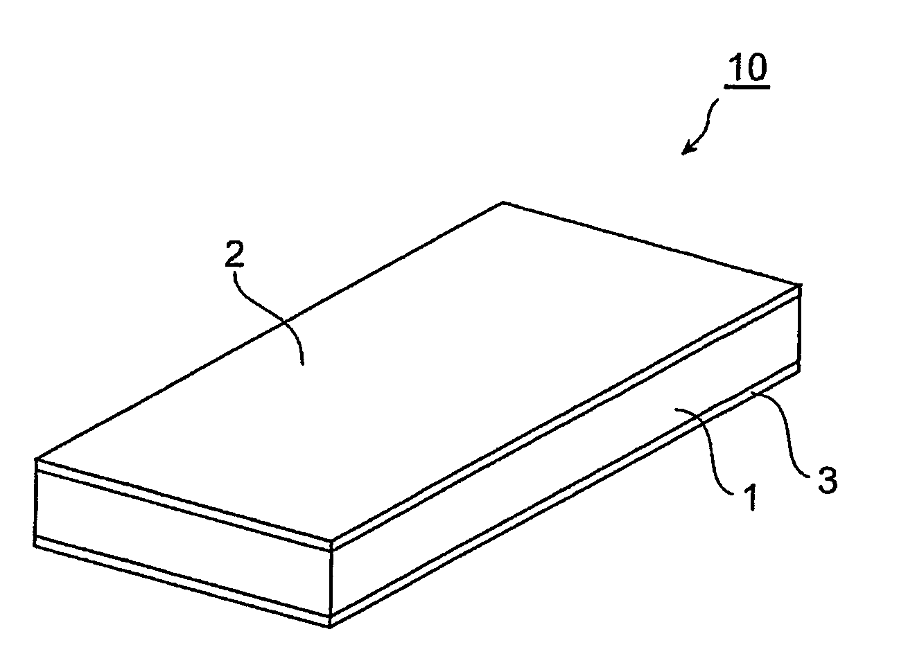
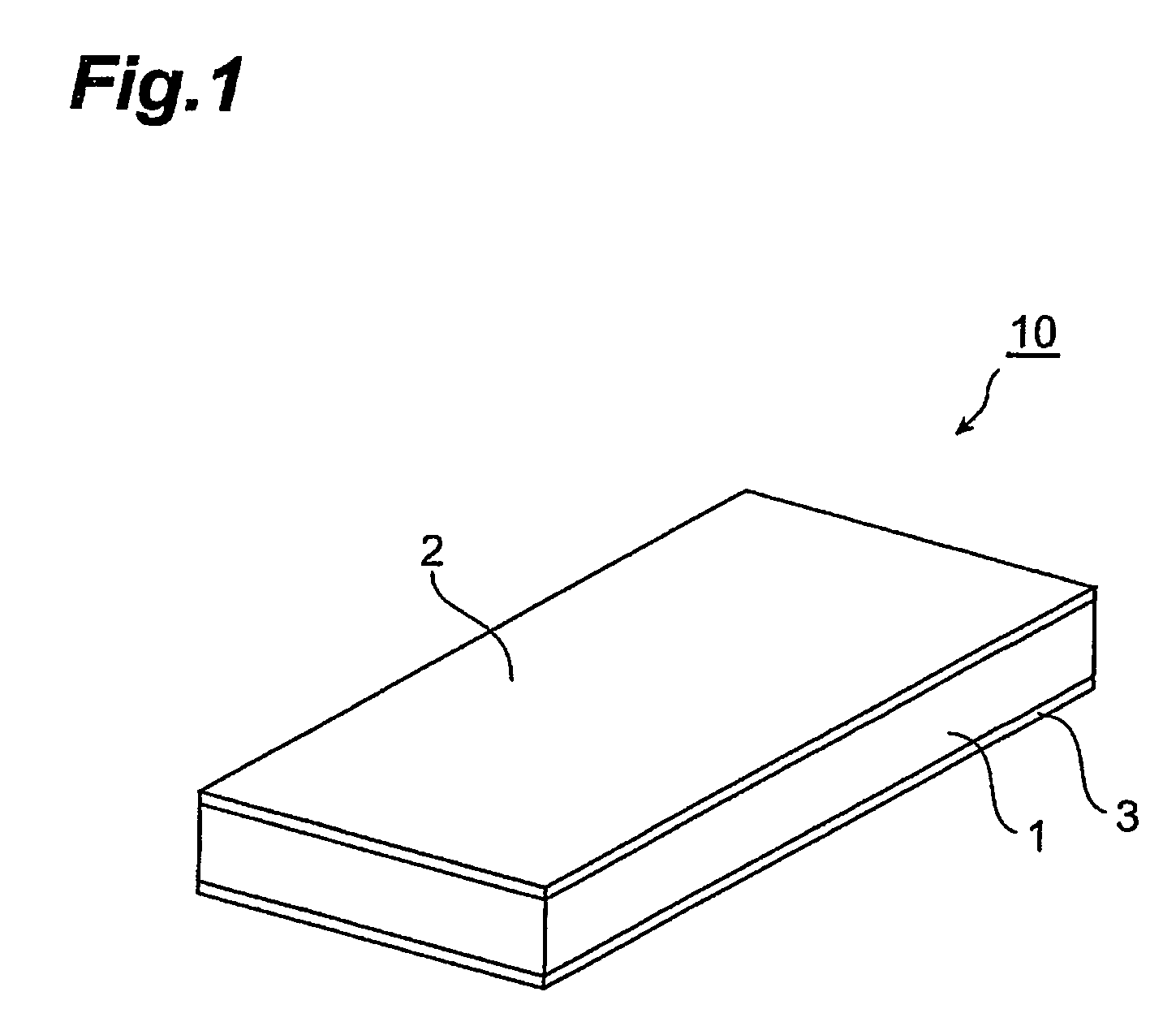
Resin composition for forming thermistor body, and thermistor
a technology of thermistor body and resin composition, which is applied in the direction of positive temperature coefficient thermistors, non-metal conductors, conductors, etc., can solve the problems of large variation of resistance value after heat treatment, impaired operating stability, and difficulty in reducing room temperature resistance, so as to achieve superior operating stability and reduce room temperature resistance. , the effect of large change ratio of resistance valu
- Summary
- Abstract
- Description
- Claims
- Application Information
AI Technical Summary
Benefits of technology
Problems solved by technology
Method used
Image

Examples
example 1
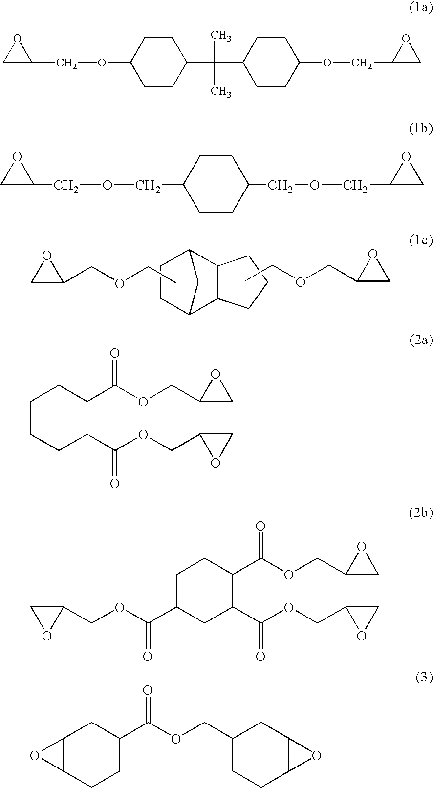
[0075]A resin composition was prepared using “E4080S” (product name of Asahi Denka Kogyo K.K., epoxy equivalents 210 g / eq.) which is an epoxy resin expressed by the aforesaid chemical formula (1a) as the cycloaliphatic epoxy resin, “B570” (product name of New Japan Chemical Co., acid anhydride equivalent 168 g / eq.) which is an acid anhydride curing agent as the curing agent, “PN-40J” (product name of Ajinomoto Fine Techno Co.) which is an epoxy resin amine adduct as the curing promoter, and “Type 255 nickel powder” (product name of INCO, average particle diameter 2.2-2.8 μm, apparent density 0.5-0.65 g / cm3, specific surface area 0.68 m2 / g) which comprises filamentous nickel particles as the electrically conducting particles. Specifically, a mixture obtained by adding 64 mass parts of the curing agent B570 and 1 mass part of the curing promoter PN-40J to 100 mass parts of the cycloaliphatic epoxy resin E4080S was stirred with a stirrer, nickel particles were added to this mixture to ...
example 2
[0080]A thermistor was obtained as in Example 1, except that “E4085S” having the structure expressed by the aforesaid chemical formula (1b) (product name of Asahi Denka Kogyo K.K., epoxy equivalents 145 g / eq.) was used as the cycloaliphatic epoxy resin, and the blending amount of the curing agent B570 was 93 mass parts.
[0081]For the obtained thermistor, from the temperature-resistance curve obtained in the same way as in Example 1, it was found that the initial room temperature resistance value was 2.0×10⁻³Ω (resistivity: 1.3×10⁻²Ωcm), and that the change ratio of resistance value was a factor of 107. The room temperature resistance of the thermistor after heating and cooling was 2.0×10⁻³Ω (resistivity: 1.3×10⁻²Ωcm), and remained at approximately the same level as the initial room temperature resistance.
[0082]To separately evaluate heat resistance, the thermistor obtained as described above was left at a high temperature of approximately 200° C., taken into an environment at room te...
example 3
[0083]A thermistor was obtained as in Example 1, except that “E4088S” having the structure expressed by the aforesaid chemical formula (1c) (product name of Asahi Denka Kogyo K.K., epoxy equivalents 170 g / eq.) was used as the cycloaliplatic epoxy resin, and the blending amount of the curing agent B570 was 79 mass parts.
[0084]For the obtained thermistor, from the temperature-resistance curve obtained in the same way as in Example 1, it was found that the initial resistance value was 2.0×10⁻³Ω (resistivity: 1.3×10⁻²Ωcm), and that the change ratio of resistance value was a factor of 106.The room temperature resistance of the thermistor after heating and cooling was 3.0×10⁻³Ω (resistivity: 1.9×10⁻²Ωcm), and remained at approximately the same level as the initial room temperature resistance.
[0085]To separately evaluate heat resistance, the thermistor obtained as described above was left at a high temperature of approximately 200° C., taken into an environment at room temperature, and its...
PUM
| Property | Measurement | Unit |
|---|---|---|
| thickness | aaaaa | aaaaa |
| thickness | aaaaa | aaaaa |
| apparent density | aaaaa | aaaaa |
Abstract
Description
Claims
Application Information
 - R&D Engineer
- R&D Manager
- IP Professional
- Industry Leading Data Capabilities
- Powerful AI technology
- Patent DNA Extraction
Browse by: Latest US Patents, China's latest patents, Technical Efficacy Thesaurus, Application Domain, Technology Topic, Popular Technical Reports.
© 2024 PatSnap. All rights reserved.Legal|Privacy policy|Modern Slavery Act Transparency Statement|Sitemap|About US| Contact US: help@patsnap.com