Circuit and method for detecting address in pre-groove (ADIP) signal in wobble detection system of optical disc apparatus
a detection system and optical disc technology, applied in the field of circuits for detecting an adip (address in pregroove) signal in a wobble detection system and a method for detecting an adip signal, can solve the problems of reducing recording quality, unable to read data recorded on dvd+r/rw disk, etc., and achieves correct and rapid detection of discontinuous points and simple configuration
- Summary
- Abstract
- Description
- Claims
- Application Information
AI Technical Summary
Benefits of technology
Problems solved by technology
Method used
Image


Examples
first embodiment
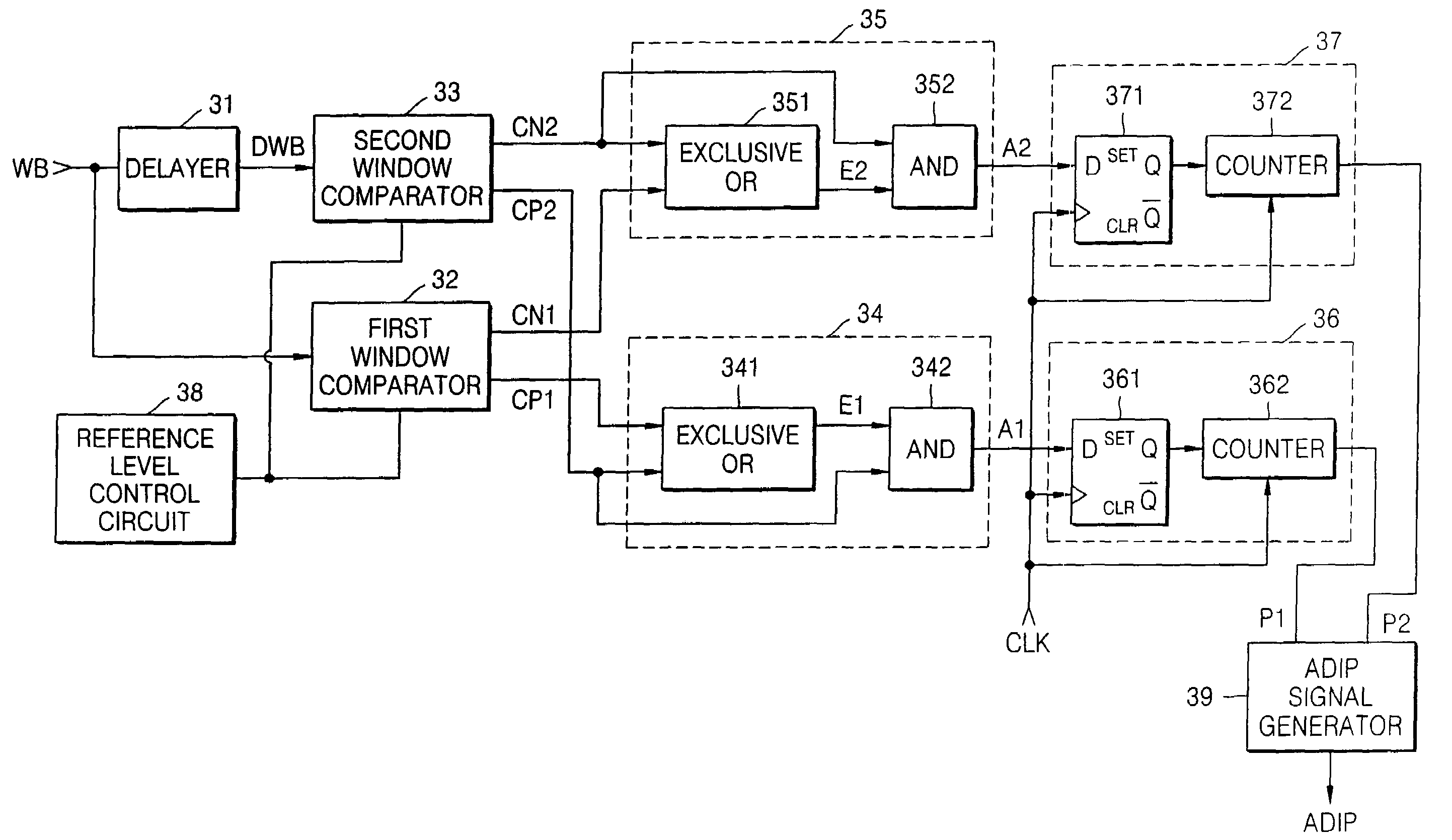
[0035]FIG. 3 is a block diagram of an ADIP (address in pre-groove) signal detection circuit according to the present invention.
[0036]Referring to FIG. 3, the ADIP signal detection circuit according to the first embodiment of the present invention includes a delayer 31, a first window comparator 32, a second window comparator 33, a first edge detection circuit 34, a second edge detection circuit 35, a first discontinuous point determination circuit 36, a second discontinuous point determination circuit 37, a reference level control circuit 38, and an ADIP signal generator 39.
[0037]The delayer 31 delays a wobble signal WB received via a wobble detection circuit (not shown) by a predetermined time period. The delayer 31 can include, for example, a low-pass filter (LPF) or a digital phase delay device. Here, the delay time of the delayer 31 is related to the response speed of the signal. If the delay time is too long, the discontinuous point may not be detected correctly. Therefore, the...
second embodiment
[0060]FIG. 6 is a block diagram of an ADIP signal detection circuit according to the present invention.
[0061]Referring to FIG. 6, the ADIP signal detection circuit according to a second embodiment of the present invention includes a window comparator 61, a first edge detection circuit 62, a second edge detection circuit 63, a first discontinuous point determination circuit 64, a second discontinuous point determination circuit 65, a reference level control circuit 66, and an ADIP signal generator 67.
[0062]The ADIP signal detection circuit according to the second embodiment performs the same operation as the ADIP signal detection circuit according to the first embodiment shown in FIG. 3, however, has a different configuration.
[0063]The window comparator 61 compares a wobble signal WB with a positive reference level REFP and generates a first comparison signal CP. Also, the window comparator 61 compares the wobble signal WB with a negative reference level REFN and generates a second c...
third embodiment
[0074]FIG. 7 is a block diagram of an ADIP signal detection circuit according to the present invention.
[0075]Referring to FIG. 7, the ADIP signal detection circuit according to the third embodiment of the present invention includes a differentiator 71, a window comparator 72, an ADIP signal generator 73, and a reference level control circuit 74.
[0076]The differentiator 71 receives a wobble signal WB input via the wobble detection circuit (not shown) and differentiates the received wobble signal WB in response to a control signal CON. Here, to obtain a correct signal, a low-pass filter (LPF) (not shown) can be connected to an output terminal of the differentiator 71, as necessary.
[0077]The window comparator 72 compares an output signal DO of the differentiator 71 with a positive reference level REFP and generates a first comparison signal CP. Also, the window comparator 72 compares an output signal of the differentiator 71 with a negative reference level REFN and generates a second c...
PUM
| Property | Measurement | Unit |
|---|---|---|
| time | aaaaa | aaaaa |
| time period | aaaaa | aaaaa |
| delay time | aaaaa | aaaaa |
Abstract
Description
Claims
Application Information