Biometric imaging device compensating for non-biometric parameters

Active Publication Date: 2007-09-18
ACTIVCARD IRELAND
View PDF9 Cites 5 Cited by
  • Summary
  • Abstract
  • Description
  • Claims
  • Application Information

AI Technical Summary

Problems solved by technology

In general, there are two types of errors associated with fingerprint identification.
A Type II error occurs when there is sufficient similarity between fingerprints of two individuals that one is mistaken for the other.
A Type I error occurs for a variety of reasons, and refers to when an individual is not identified even though the individual is an authorized user registered with the system.
It has been suggested that the underlying cause of errors in fingerprint analysis is that the amount of data from a fingerprint is too limited for it to be used in a biometric identification system involving a large number of users.
The above-mentioned causes for failures in fingerprint verification are closely related to the applied imaging and analyzing techniques, and are typically responsible for Type II errors.
There are, however, other sources for identification errors, which are primarily of a non-biometric nature.
Furthermore, the hygienic conditions of a hand, and more particularly that of the fingertip to be imaged, are also factors for possible interference in properly imaging a fingerprint.
All this causes problems in a reproducibility of a fingerprint imaging process, and in turn leads to an increase in Type I or false reject error rates.

Method used


Image

  • Biometric imaging device compensating for non-biometric parameters
  • Biometric imaging device compensating for non-biometric parameters
  • Biometric imaging device compensating for non-biometric parameters

Examples


first embodiment

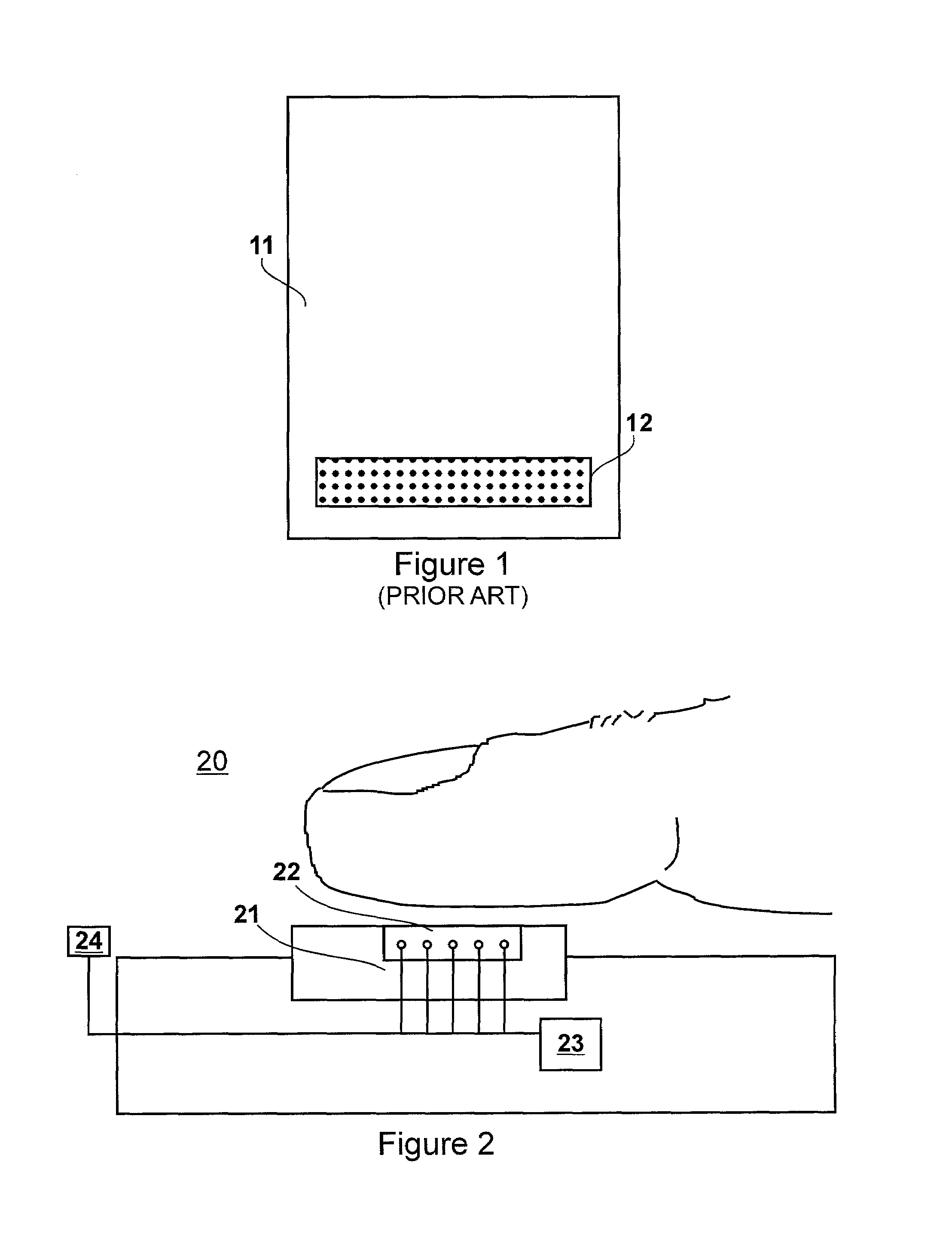
[0031]Referring to FIG. 2, a simplified diagram of a biometric imaging device according to the instant invention is shown. The biometric imaging device is based on the above-described capacitive contact swipe imager. Alternatively, the present invention is based on another type of contact imager, another type of swipe imager, an optical imager, a thermal imager, or the like.

[0032]The biometric imaging device 20 includes a sensing pad 21, which comprises a linear capacitive sensing array 22. The biometric imaging device 20 further includes a processor 23, as well as a sensor 24 for sensing external conditions. The parameters sensed by the sensor include ambient temperature and ambient humidity. Both the linear capacitive sensing array 22 as well as the sensor 24 are connected to the processor 23. A biological surface, for example a fingertip, is passed over the sensing pad 21, and a plurality of partial images is captured by the linear capacitive sensing array 22, and processed by th...

second embodiment

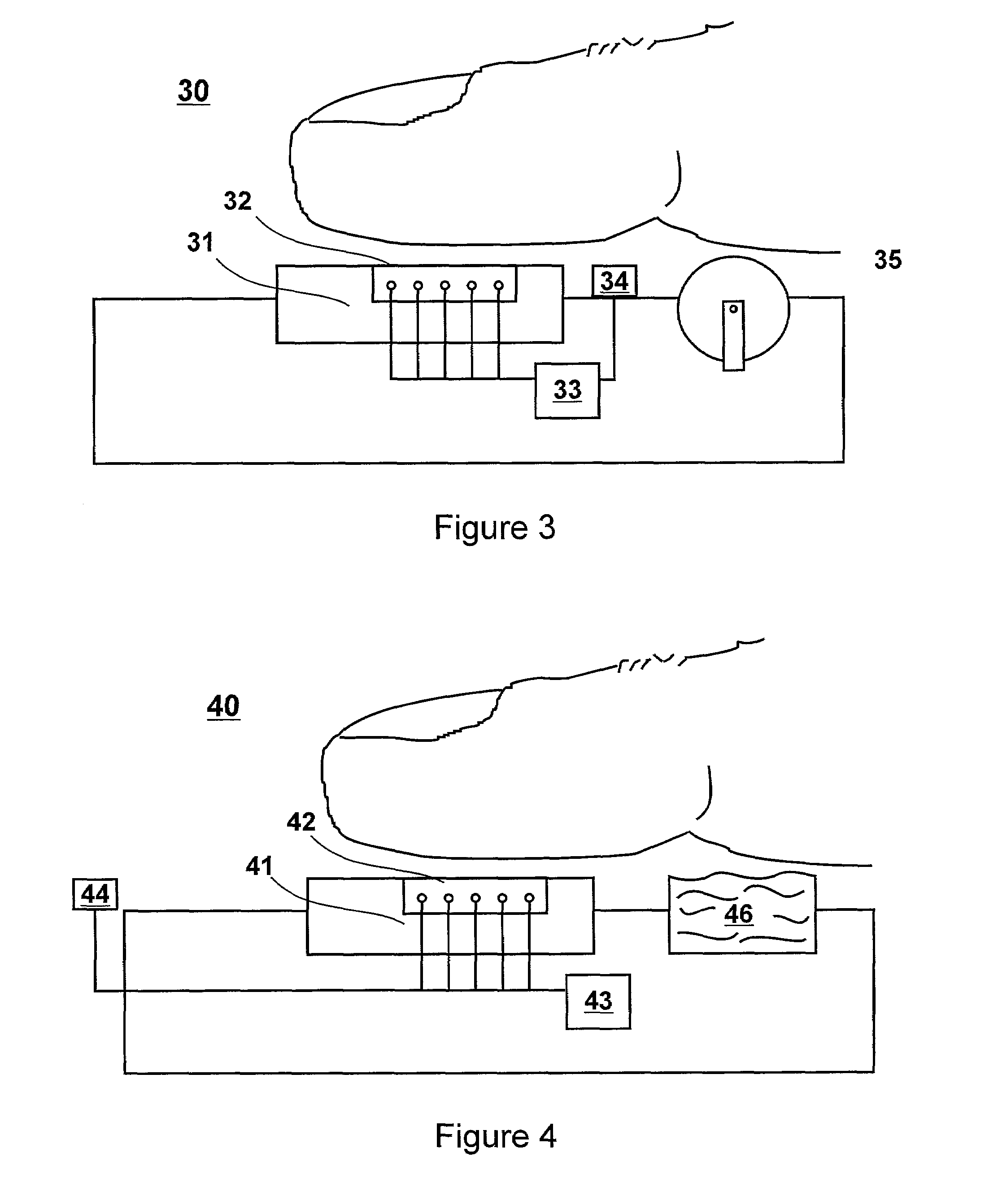
[0034]Referring to FIG. 3, a simplified diagram of a biometric imaging device according to the instant invention is shown. The biometric imaging device 30 again includes a sensing pad 31, which comprises a linear capacitive sensing array 32, a processor 33, as well as a sensor 34. The sensor 34 is for sensing the conditions of the biological surface to be imaged. The biometric imaging device 30 further includes a roller 35 for guiding a biological surface to be imaged, for example a fingerprint, towards the linear capacitive sensing array 32. The sensor 34 is disposed between the sensing pad 31 and the roller 35. This way, it is most likely that the data sensed by the sensor 34 corresponds to the condition of the biological surface sensed by the linear capacitive sensing array 32. Both the linear capacitive sensing arrays 32 as well as the sensor 34 are connected to the processor. When in use, a biological surface to be imaged, such as a fingertip, is positioned on the roller 35 and...

fourth embodiment

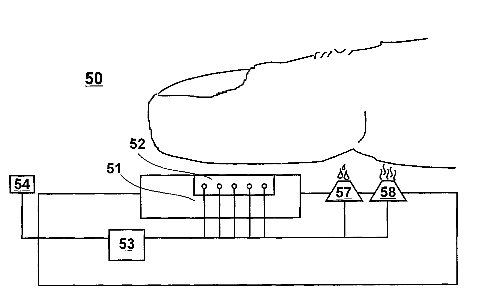
[0036]Referring to FIG. 5, a simplified diagram of a biometric imaging device according to the present invention is shown. The biometric imaging device 50 includes a sensing pad 51, comprising a linear capacitive sensing array 52, a processor 53 and a sensor 54. The sensor detects the ambient temperature and the ambient moisture level for the biometric imaging device. Alternatively, the sensor 54 is installed in a way, so that the sensor 54 detects the physiological conditions of a biological surface to be imaged, such as a fingertip, the physiological conditions being for example the temperature and the dryness of the fingertip. Optionally, a roller is added to the biometric imaging device 50. Further optionally, a cleaning station is added to the biometric imaging device 50. The sensor 54 as well as the linear capacitive sensing array 52 are connected to the processor 53. Further, two compensating devices 57 and 58 are added to the biometric imaging device. The compensating device...


PUM


Abstract

Provided is a biometric imaging device for imaging a biological feature, which includes a sensor for detecting an environmental parameter other than relating to surface topology of said biological feature. The detected environmental parameters like temperature and humidity levels are utilized in image reconstruction to eliminate erroneous structures caused by the environmental conditions. There is also provided a biometric imaging device, which includes a preparation device for use prior to sensing a biometric image. The preparation device is used for conditioning a parameter of the biometric information source, and / or for cleaning the biometric information source.

Description

[0001]This application claims the benefit from U.S. Provisional Patent Application No. 60 / 305,187 filed on Jul. 16, 2001.FIELD OF THE INVENTION[0002]This invention relates generally to biometric imaging devices and more particularly to biometric imaging devices for imaging biometric surfaces capable of compensating images according to non-biometric parameters.BACKGROUND OF THE INVENTION[0003]With the increasing importance of personal identification for the purpose of security in remote transactions in today's world of electronic communication, biometric identification techniques are rapidly evolving into a pervasive method for personal verification. Among the different biometrics proposed for such a purpose, such as fingerprints, hand prints, voice prints, retinal images, handwriting samples and the like, fingerprint analysis is amongst the best studied biometric techniques. Fingerprint sensing and matching is a reliable and thus widely used practice for personal identification or v...

Claims


Application Information

Patent Timeline
IPC IPC(8): G06K9/00G06V40/13
CPCG06K9/00013G06K9/036G06V40/13G06V10/993
Inventor HAMID, LAURENCE
Owner ACTIVCARD IRELAND
Why Eureka
Try Eureka