Network monitoring device and method

a network monitoring and network monitoring technology, applied in the field of network monitoring devices and methods, can solve the problems of inability to correctly transfer packets to all nodes exceeding the limit, the routing table cannot be stored that exceeds the capacity of the built-in memory, and the inability to ensure the inter-node communication of the network

Inactive Publication Date: 2007-09-18
FUJITSU LTD
View PDF21 Cites 26 Cited by
  • Summary
  • Abstract
  • Description
  • Claims
  • Application Information

AI Technical Summary

Benefits of technology

[0016]The present invention was created in view of the above circumstances, and an object thereof is to provide network monitoring device and method capable of giving an alarm to the user before a guaranteed limit of packet routing is exceeded.

Problems solved by technology

For example, the router is unable to store a routing table that exceeds the capacity of the built-in memory thereof.
Thus, the router has its own limit on the number of destination nodes which the router can identify, and therefore, cannot correctly transfer packets to all of nodes exceeding the limit.
If there exists even a single router which can identify fewer nodes than the number of nodes connected to the network, then inter-node communications of the network cannot be guaranteed.
Also, since the routing information is exchanged between nodes at regular intervals, increase in the number of nodes connected to the network inevitably entails an increase of communication traffic of the transmission path.
If the communication traffic exceeds the transmission capacity of the transmission path, appropriate transmission and reception of packets cannot be guaranteed.
In the case of a large-scale network, however, it is difficult to correctly determine the number of nodes up to which packet routing can be guaranteed, by investigating all network environments.
For example, when the network is to be extended, the routing tables of all routers on the network may be looked up to determine whether the number of nodes exceeds the limit or not, but such work is extremely complicated and consumes much labor and time.
However, where there arises a need for a substantial change of the network configuration or the number of nodes, for example, where independently operated networks are connected together, all network environments need to be examined, requiring considerable time and labor.

Method used


Image

  • Network monitoring device and method
  • Network monitoring device and method
  • Network monitoring device and method

Examples


first embodiment

[0053]In the first embodiment, the function of the network monitoring device 1 is incorporated into a node having a router function.

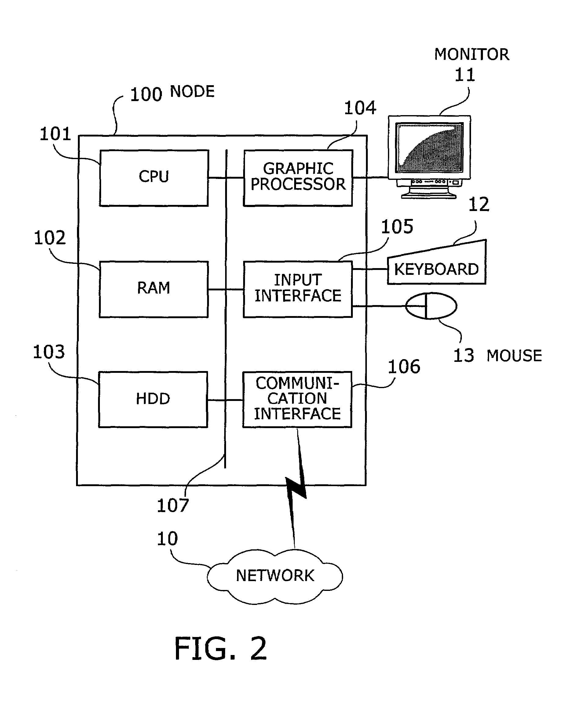
[0054]FIG. 2 shows an example of a hardware configuration of a node used in the first embodiment. The node 100 includes a CPU (Central Processing Unit) 101 whereby the entire node is controlled. To the CPU 101 are connected, via a bus 107, a RAM (Random Access Memory) 102, a hard disk drive (HDD) 103, a graphic processor 104, an input interface 105, and a communication interface 106.

[0055]The RAM 102 temporarily stores at least part of OS (Operating System) programs and application programs executed by the CPU 101. Also, the RAM 102 stores various data necessary for the processing by the CPU 101. The HDD 103 stores the OS and application programs.

[0056]The graphic processor 104 is connected with a monitor 11. In accordance with instructions from the CPU 101, the graphic processor 104 causes the monitor 11 to display an image on a screen thereof. The inp...

second embodiment

[0120]The second embodiment will be now described. In the second embodiment, the allowable values and the precautionary values can be set by the user's input operation.

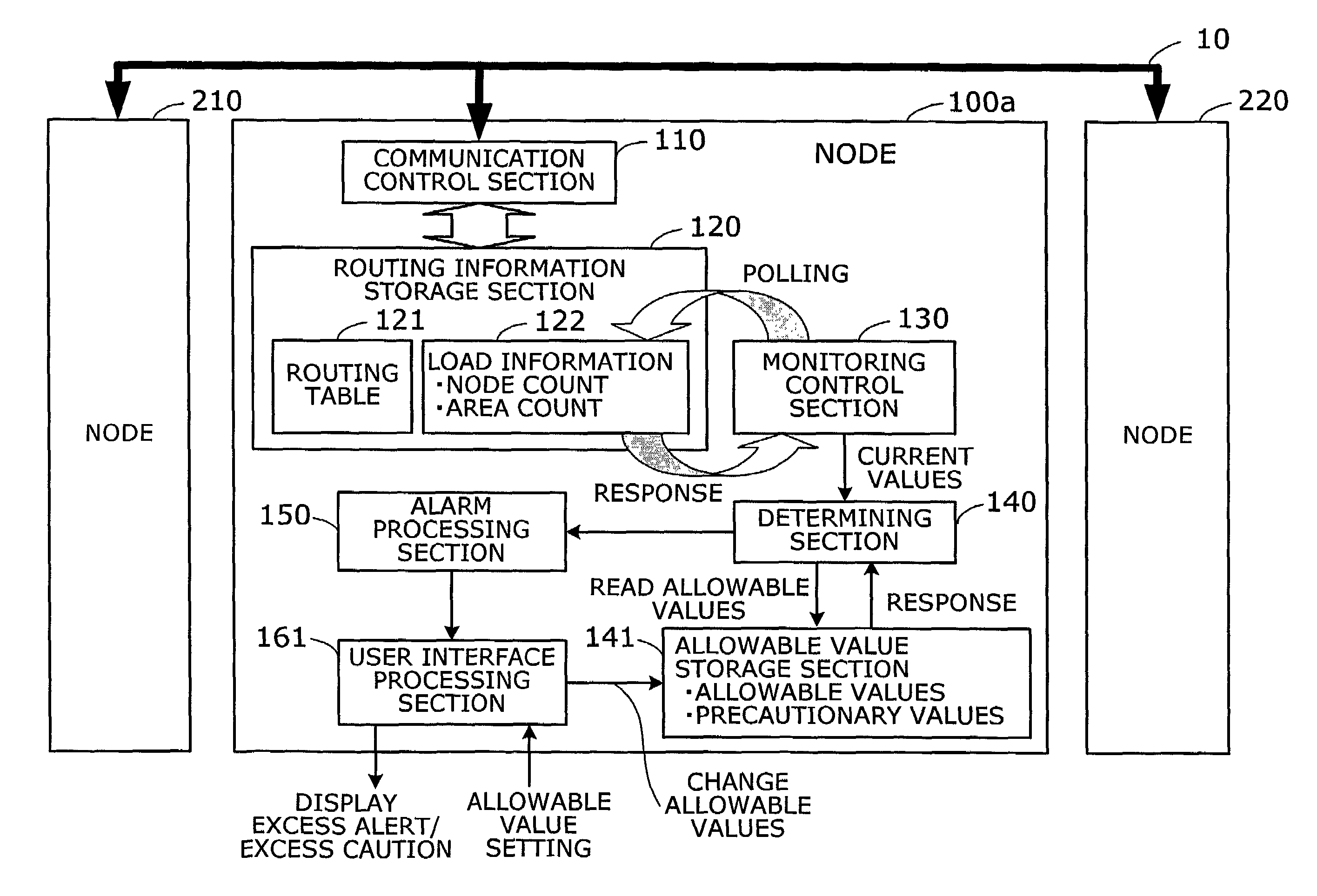
[0121]FIG. 10 is a functional block diagram illustrating the function of a network device according to the second embodiment. The configuration of the second embodiment is almost identical with that of the first embodiment; therefore, in FIG. 10, identical reference numerals are used to denote elements with the same functions as those in the first embodiment shown in FIG. 3, and description of such elements is omitted.

[0122]A node 100a according to the second embodiment differs from the node of the first embodiment only in the function of a user interface processing section 161. The user interface processing section 161 has, in addition to the function of the user interface processing section 160 of the first embodiment, a function whereby information can be set in the allowable value storage section 141 in response t...

third embodiment

[0124]The third embodiment will be now described. In the third embodiment, the user is periodically notified of the numbers of connected nodes and areas.

[0125]FIG. 11 is a functional block diagram illustrating the function of a network device according to the third embodiment. The configuration of the third embodiment is almost identical with that of the first embodiment; therefore, in FIG. 11, identical reference numerals are used to denote elements with the same functions as those in the first embodiment shown in FIG. 3, and description of such elements is omitted.

[0126]A node 100b according to the third embodiment differs from the node of the first embodiment in the functions of a monitoring control section 131 and user interface processing section 162. In FIG. 11, the determining section 140 and the alarm processing section 150 (cf. FIG. 3) provided in the first embodiment are omitted.

[0127]The monitoring control section 131 periodically polls the routing information storage sec...


PUM


Abstract

Network monitoring device and method whereby the user can be given an alarm before a guaranteed limit of packet routing is exceeded. Counting section counts the number of nodes based on packets exchanged between the nodes, and comparing section compares the node count with an allowable value. If the node count is larger than the allowable value, alarm output section outputs a message that the node count is excessively large.

Description

BACKGROUND OF THE INVENTION[0001]1. Field of the Invention[0002]The present invention relates to network monitoring device and method, and more particularly, to network monitoring device and method for monitoring load on a network.[0003]2. Description of the Related Art[0004]To an OSI (Open Systems Interconnection)-based or TCP / IP (Transmission Control Protocol / Internet Protocol)-based network are connected various network devices such as a SONET (Synchronous Optical Network) or SDH (Synchronous Digital Hierarchy) transmission device, an ATM (Asynchronous Transfer Mode) exchange, a router and terminal units. Such network devices connected to the network are called nodes.[0005]FIG. 17 shows an example of a conventional network configuration. In FIG. 17, an OSI network is illustrated by way of example. The OSI network comprises a plurality of areas 910, 920 and 930. The area 910 includes nodes 911 and 912. The area 920 includes nodes 921 to 923, and the area 930 includes nodes 931 and...

Claims


Application Information

Patent Timeline
Patent Type & Authority Patents(United States)
IPC IPC(8): G06F15/173H04L69/40
CPCH04L41/06H04L43/00H04L43/10H04L43/16
Inventor KAWASAKI, ATSUSHISHIMADOI, TORU
Owner FUJITSU LTD
Why Eureka
Try Eureka